Two Apparatus Classes, Two Design Intents
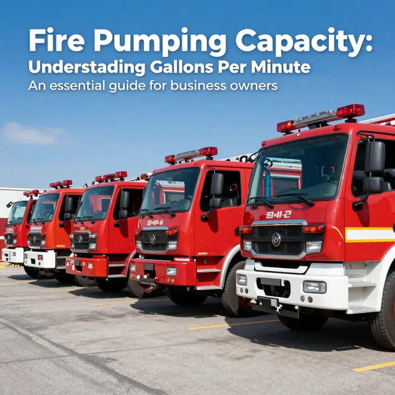
Buyers and builders still compare a tactical water tender with a municipal pumper on chassis class, gross vehicle weight, or wheelbase. Those numbers describe the truck. They miss the engineering distinction, which is the mission. A tender exists to move water to places that have no hydrant: 2,000 to 4,000 gallons on board, some units above 5,000. Its transfer pump, dump valves, and tank geometry are sized for getting that water out quickly, into portable tanks or a relay pumper. A pumper is built around rated flow instead. Its fire pump, commonly rated 1,250 to 2,000 gpm, feeds attack lines, appliances, and master streams from a pressurized source, and the 500 to 1,000 gallons in the tank is a buffer for the first minutes rather than a reserve. Body space goes to hose beds, compartments, and pump access, not to a large water envelope. Either class can ride the same commercial chassis; what separates them is the job each is engineered to do first. For a department writing a tanker spec, that decision should be settled before anyone orders a component.
Baffle Spacing and Fill Rate Are Coupled
The two classes converge on the same problem: tank baffle spacing and fill rate get written as separate lines on a specification sheet, yet they interact. Baffle count and longitudinal spacing set how much surge the tank shell, subframe, and chassis rails must absorb; fill rate sets how fast the water mass is allowed to arrive. Tight spacing shortens the wave and lowers the impulse, at the cost of plate mass, payload, and compartment volume. A faster fill cuts exposure time at the fill point but concentrates the transient mass shift, and baffles, vents, and baffle-to-shell welds see higher surge pressures. Move either variable and payload distribution changes, along with the margin left for pump, hose, and equipment weight.
No configuration is optimal in the abstract. A defensible specification matches baffle geometry and fill rate to the duty cycle, the route profile, the water-supply tactics, and the flow the pump has to hold once the tank runs dry.
Baffle Spacing Engineering Fundamentals
Of all the dimensions on a tank drawing, baffle spacing most directly determines how the water load behaves while the truck is moving. Spacing sets the length of each compartment, and that length, measured against tank depth and width, controls surge amplitude, the size of the free-surface effect, and what load reaches the chassis. The same dimension also decides plate mass, usable volume, how much external reinforcement is needed, vent area, and where the welds will fatigue.
How Baffle Spacing Subdivides the Tank into Compartments
Transverse baffles cut the tank into discrete compartments. Tank baffle spacing, whether quoted as clear spacing or center-to-center, fixes the length of water that can move as a single body when the driver brakes, turns, or takes a grade. That makes spacing a design variable, not a fabrication detail.
Two ratios do the work: compartment length to liquid depth (L/D) for fore-aft surge, and compartment width to depth for side-to-side surge. A long compartment lets a traveling wave develop along its full length, and surge amplitude grows roughly with the length available. Bring L/D to about 1 or below and the fundamental standing wave no longer fits inside the compartment; peak amplitude, and the momentum handed to the structure, drop sharply. The lateral case behaves the same way, which is why a tank wider than it is deep usually gets a longitudinal divider.
In practice, compartment length is held at or below liquid depth, and lateral subdivision is added once tank width passes that threshold. Representative water tanker fire truck tank arrangements show how those proportions change with body style.
Free-Surface Effect, Surge Amplitude, and Load Transfer
Tighter spacing shrinks each free surface. The free-surface moment about the pitch and roll axes scales with breadth times the cube of surface length, so halving the length of a compartment cuts the effective free-surface moment of that portion by roughly a factor of eight. That reduction, more than the added baffle mass, is where the stability and load-transfer benefit comes from.
Smaller compartments also cap tank sloshing amplitude and push the slosh frequency up, away from the excitation produced by braking and suspension pitch. On the road that means lower peak dynamic load transfer into the chassis, less fore-aft wheel-load oscillation, less cycling in springs and frame, and axle loads that stay predictable, which matters most with a part-full tank being shuttled between draft sites at low level.
Structural Mass, Usable Volume, and Wall Reinforcement
Every baffle is paid for out of payload. Plate, stiffening, and weld volume all consume capacity inside a fixed envelope, and on a short-wheelbase tactical tender the gross vehicle weight rating is already committed to pump, hose, and tools. Some of that cost comes back structurally: baffles act as internal diaphragms, shortening the unstiffened span of the shell and head plates.
That bracing lets a designer keep shell thickness and external reinforcement down, but it concentrates load where the baffle attaches. With tight spacing the shell panel between baffles is short, and hoop and racking loads run into the baffle perimeter. With wide spacing the plate field and external reinforcement have to carry more.
Venting, Transfer Openings, and Weld Fatigue
Baffles need venting or transfer openings sized for the fill and drawdown rates the truck will actually see. The openings equalize head between compartments during filling and drafting. Undersize them and the baffle becomes a pressure boundary: a differential hydrostatic head builds across it on every fill, and the baffle and its welds take the load.
Weld detail then sets the service life. Each baffle-to-shell and baffle-to-baffle joint is a fatigue location, cycled by filling and drawdown, road vibration, and surge pressure. Continuous welds with controlled toe geometry at the ends and corners resist cracking better than intermittent stitching in these restrained regions. Fill rate and transfer-opening area therefore belong in the same sentence of a spec.
| Design change | Surge amplitude | Free-surface effect | Structural mass | Usable volume |
|---|---|---|---|---|
| Closer baffle spacing | Reduced | Reduced | Increased | Reduced |
| Wider baffle spacing | Increased | Increased | Reduced | Increased |
Side-by-Side Baffle Configuration Comparison
The table below compares baffle architectures across municipal pumpers and tactical water tenders, the same water tanker fire truck platform engineered to two very different duty cycles.
| Configuration | Typical Compartment Spacing | Baffle Type | Sloshing Control | Structural Mass Penalty | Usable Volume Impact | Typical Application |
|---|---|---|---|---|---|---|
| Single full-length tank, no baffles | Uninterrupted; full shell length | None | Poor; long-period free-surface motion | Minimal; lightest shell | Maximum nominal capacity | Short-haul municipal booster tanks |
| Longitudinal centerline baffle only | Continuous centerline, partial depth | Longitudinal, partial-depth | Low-moderate; lateral control only | Low; ~2-3% tare increase | Minimal dead volume | Low-CG oval tankers, urban response |
| Wide-spaced transverse baffles | 48-96 in bays | Transverse, single-wall | Moderate; limits long-wave surge | Low; ~2-4% tare increase | Near-full; negligible dead volume | Standard municipal pumper tanks |
| Close-spaced transverse baffles (subdivided compartments) | 24-36 in bays | Transverse, subdivided | High; rapid surge damping | Moderate; ~5-8% tare increase | Moderate; inter-baffle dead volume | Tactical tenders on graded and off-road routes |
| Combined transverse and longitudinal baffles | 24-48 in bays, split on centerline | Transverse and longitudinal grid | Very high; multi-axis control | High; ~8-12% tare increase | Reduced; corner and grid dead volume | High-CG tenders, mountain and winding access |
| Baffle with transfer opening | 36-48 in bays, sized orifices | Transverse with transfer ports | Tuned; controlled cross-flow equalization | Moderate; reinforced port collars | Slight; port area offsets dead volume | Tenders balancing fast fill against fast dump |
Values are typical of North American apparatus practice and are indicative rather than prescriptive – confirm baffle spacing, mass penalty, and usable volume against the tank builder’s calculations and NFPA 1901/1906 stability and load requirements before spec writing.
Fill Rate Fundamentals
Fill rate is a volumetric flow: net gallons delivered into the tank per minute (gpm), calculated as tank volume change divided by elapsed time. It describes a system rather than a pump, and it means nothing without the test conditions, which are fill pressure at the port, hose or pipe length and diameter, vent configuration, and tank level at the moment of measurement. Transfer rate uses the same units for water moving inside the apparatus or between vehicles: pump to tank, tank to pump, tender to pumper. Onboard transfer plumbing is usually smaller than the external fill connection, so the transfer number is often the lower of the two, and it is the one that sets how fast a tactical water tender can top up a municipal pumper during a shuttle.
The Variables That Set the Number
Fill rate comes down to a short list of physical variables, all of them either on the specification sheet or measurable in the field:
- Fill port diameter (typically 2.5 in, 3 in, 4 in, 5 in, or 6 in Storz or threaded)
- Internal piping bore and the number and radius of bends between port and tank inlet
- Valve type and position: butterfly, gate, ball, or check, and whether it opens fully
- Vent capacity, including vent size, baffle clearance at the top of the compartment, and any flame arrestor restriction
- Pump curve performance at the specific pressure required to fill, not at the pump’s rated point
- Hose friction loss across the supply line at the target flow
- Source mode: hydrant pressure, relay pumping, or an onboard transfer pump
Four constraints dominate in practice, roughly in this order:
- The smallest bore anywhere in the water path, which sets the velocity ceiling and therefore the flow ceiling.
- Vent capacity, because air has to leave the tank as fast as water enters it; an undersized vent turns a fast fill into a pressurized fill and trips the relief.
- Net pressure available at the fill port after friction loss in the hose, fittings, and valves.
- Valve type and position, since a partly open butterfly valve or a check valve with a high cracking pressure removes pressure that no upstream pump can recover.
Gravity Dump Rate Versus Pressurized Fill Rate
Gravity dump depends on head alone. Flow through a dump valve follows an orifice relationship proportional to the square root of the depth above the outlet, so the rate peaks with a full tank and falls as the level drops: a 6 in gravity dump that moves roughly 1,000 gpm at full head may deliver about half that at quarter depth. Pressurized fill is a different problem. There the flow is set by where the supply system curve, falling with flow, meets the fill piping curve, rising with flow. Inside the vent and relief limits, a pressurized fill holds a fairly flat rate across the fill, which is why fill rate for a tactical water tender is quoted at a stated port pressure rather than as an average.
Why a High Pump Rating Does Not Guarantee Fill Rate
A 1,500 gpm rating describes what a municipal pumper can deliver at rated pressure and suction through the main pump discharge. It says nothing about the fill circuit, which has its own bore, fittings, relief setting, and vent limit. The same pump may push only 500 gpm through a 3 in fill line at 50 psi, because friction loss climbs steeply with flow and the vent stops accepting air. Put attack lines on the pump at the same time and the pressure left at the fill pipe falls further. Ask for a documented fill rate at a named port pressure, hose length, and vent configuration, and treat the pump rating as context.
| Variable | Direction of effect on fill rate |
|---|---|
| Fill port and piping bore | Larger bore raises flow approximately with the square of diameter |
| Internal bends and fittings | Added equivalent length lowers achievable flow |
| Vent capacity | Caps flow once air displacement becomes the limiting restriction |
| Valve type and position | Restricted opening or high cracking pressure reduces net head |
| Supply mode | Hydrant pressure is typically steadiest, relay pumping loses head per relay |
| Hose friction loss | Rises with flow and length; the dominant loss on long lays |
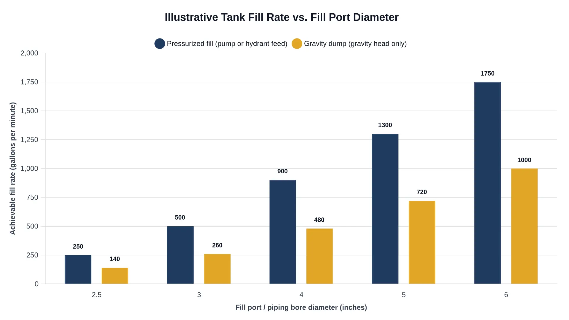
Illustrative values: pressurized fill and gravity dump rates diverge sharply as bore increases, and gravity performance degrades further as tank level falls.
Departments comparing tank configurations and connection sizes should review the available water tanker fire truck build options before locking a specification, since port size, vent area, and internal plumbing are decided at the design stage and are expensive to change afterward.
Nominal Fill and Transfer Rates by Configuration
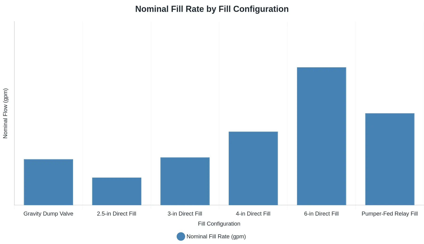
Nominal flow in gallons per minute, 0-2000 gpm scale. Values reflect chassis-rated fill hardware at rated engine speed with a static draft source; actual delivered rates vary with lift, hose length, and source capacity.
Across these six configurations, the biggest single gain comes from stepping a direct fill line from 4-inch to 6-inch, which lifts nominal throughput from roughly 800 gpm to about 1500 gpm, nearly 700 gpm for one piping change. The jump is not proportional to diameter, because capacity follows cross-sectional area (diameter squared) while friction loss falls as velocity drops, so the larger line lets the pump move water with a smaller head penalty. Smaller upgrades such as 2.5-inch to 3-inch buy only a few hundred gpm. Departments chasing short cycle times should treat 6-inch direct fill as the threshold decision on a water tanker fire truck rather than an option to add later.
Tank Sloshing and Weight Distribution
A partially filled tank is a moving mass, not a fixed one. Water with a free surface accelerates independently of the chassis, so braking, steering, and grade changes produce a phase-lagged inertial response that the structure has to absorb. That is tank sloshing in its operational form: the free surface stays level while the truck pitches or rolls beneath it, and the resulting shift moves load away from the tank’s geometric center.
Fore and aft. Under braking, water runs forward with a force proportional to free-surface mass and deceleration rate. On a tender carrying a 3,000-gallon load, that surge loads the front axle and can unload the drive axles enough to change traction and ABS behavior. A grade produces a slower version of the same shift, holding load over the wrong axle for the length of the climb.
Side to side. In a corner the liquid rolls opposite the turn, adding a dynamic roll moment to the static one and effectively lifting the working center of gravity above the tank’s geometric centroid. Steady axle loads print cleanly on a scale ticket; transient loads, which are what the suspension and frame actually see, do not.
Spacing sets the size of it. Transverse baffles break the free surface into shorter cells. Tight spacing shortens the distance the water can travel, raises its natural frequency above typical chassis response, and cuts peak force per event. Wide spacing leaves one long, unobstructed surface behaving like a single moving mass. Longitudinal baffling matters as much, because water running the length of the tank produces the largest fore-aft moment.
Fill sequence decides where the weight sits. Filling end compartments first and keeping the center sections empty holds mass closer to the axles and reduces the polar moment the frame has to resist. Filling one side or one end first produces an asymmetric load that shows up as cross-weight on the suspension and as torsional input to the frame rails.
Tank shape sets the baseline. Rectangular tanks maximize volume per dollar, with the largest flat free surface and the highest centroid. Elliptical tanks lower the center of gravity and, at equal volume, expose less free surface at a given fill level. T-tanks split the volume into a longitudinal spine and a cross tube, narrowing each lateral cell while fore-aft travel along the spine remains the dominant mode.
Tender versus pumper duty cycles. A tactical water tender spends most of its life at partial fill: drafting, shuttling, dumping, and refilling at rates that rarely hold a steady level. Its tank has to tolerate sustained free-surface activity, which is why closer tank baffle spacing and robust compartment sequencing matter more on a tender than on any other apparatus class. A municipal pumper runs near full, where the water behaves as a rigid mass, or near empty, where the free surface is too small for slosh forces to matter. Its weight-distribution problem is static and gets solved on the specification sheet; the tender’s is dynamic and gets solved in the tank design.
Either way, the same four numbers decide the design: center-of-gravity height, axle ratings, frame rail section modulus, and spring capacity, all sized against the worst transient condition rather than the parked one.
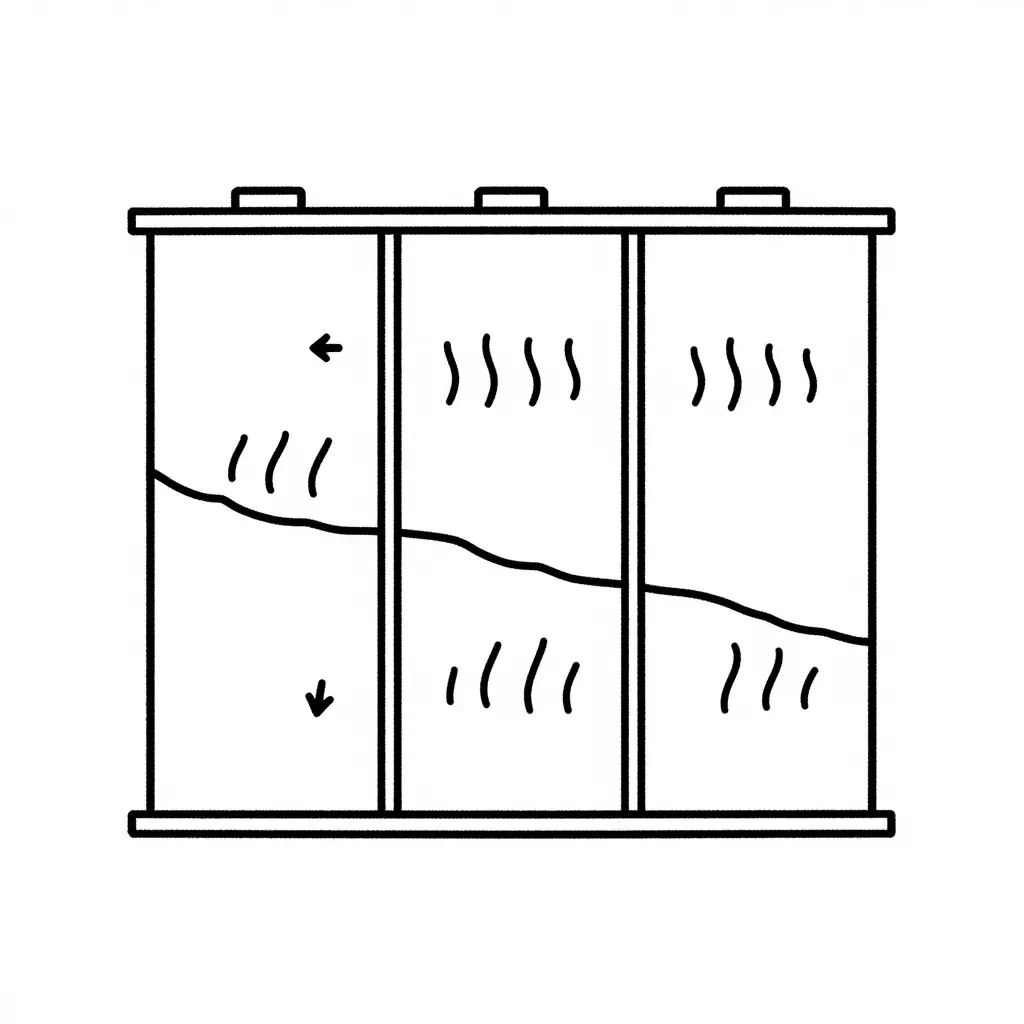
Cross-section schematic of a tank compartmented by transverse baffles, showing surge direction and how fluid travel amplitude is restrained within each bay.
Pump Performance and Plumbing Tradeoffs
A fill rate is never a tank-only figure. It falls out of a hydraulic negotiation between the water source, the plumbing bore, the vent capacity, and the pump curve of whatever is moving the water. A large tank with unmatched plumbing and venting does not raise throughput; it moves the bottleneck somewhere else.
Rate Pump Flow Against the Tank-to-Pump Bore
A pump is rated at a duty point, not at a pipe size. Undersize the suction or tank-to-pump line and the system curve steepens, so the pump runs far to the left of its published rating and a nominal 1,000 gpm pump delivers a fraction of that at the tank. Keep suction velocity low, keep runs short, and minimize elbows: every long-radius bend and every unnecessary foot of pipe behaves like a smaller bore. The pipe, not the badge on the pump, sets the ceiling.
Size the Transfer Pump for Simultaneous Duty
On a tender the transfer pump usually fills the tank and feeds a discharge line at the same time, so its rating has to cover both demands at the real duty point, not the nameplate figure at zero head. Leave margin for wear, elevation, and water temperature, and check that the pump’s preferred operating region covers the whole envelope rather than one design point.
Pay the Friction Bill Up Front
Long or undersized runs on either side of the pump cost twice: once in lost pressure, once in reduced net flow. The losses below assume lined hose and smooth pipe, water only, per 100 ft of run, with each fitting adding equivalent length.
| Bore | 300 gpm | 500 gpm | 1,000 gpm |
|---|---|---|---|
| 2.5 in | 18 psi | 50 psi | n/a |
| 3 in | 9 psi | 25 psi | n/a |
| 4 in | 2 psi | 5 psi | 20 psi |
| 6 in | <1 psi | 1 psi | 3 psi |
On the suction side the penalty is worse than lost pressure. Excess lift and friction erode net positive suction head and push the pump toward cavitation, which shows up as vibration, noise, and falling output long before anything visibly fails.
Place Valves for Fill and Discharge in Parallel
Filling and discharging at the same time is a plumbing question before it is a pump question. Gated tank fill, a check valve on the tank-to-pump line, and separate, independently controlled discharge gates let the operator split flow without backfeeding the tank or starving the discharge. A single shared valve forces an either/or choice that no crew wants to make under pressure.
Venting Caps the Achievable Fill Rate
The vent has to pass air as fast as water enters. If it cannot, the tank pressurizes, the fill line air-binds, and the fill rate collapses into a geyser at the fill tower. Vent free area is commonly sized at or above the area of the fill connection; pairing a large fill pipe with a small vent just moves the limit elsewhere. Expect the practical ceiling to be set by whichever of vent, fill line, or pump is smallest.
How the Operating Model Shifts the Constraints
A pumping-and-rolling model keeps the pump engaged and the discharge pressurized while the apparatus moves. That favors generous suction plumbing, dependable pump cooling, and a tank baffled well enough to take partial loads without excessive slosh force. A dump-and-run model treats the tank as a batch vessel, favoring large-bore gravity dump valves, fast fill connections, and plumbing sized for high instantaneous flow. Neither model is inherently faster; each pushes the constraint onto a different component, which is why a municipal pumper and a tactical water tender end up with visibly different plumbing at similar nominal ratings. Pump, manifold, valves, and vents work as one system, so it pays to review proven fire truck plumbing and pump components while the tank is being sized.
Specification Checklist: Lock Down the Variables Before You Sign
Before an order goes to the factory floor, both parties should turn every performance expectation into a measurable line item that someone will witness. The list below works for either a tactical water tender or a municipal pumper (see related water tanker fire truck configurations).
- State nominal tank capacity, usable capacity, and a written tank baffle spacing statement tied to the tank builder’s slosh-control design.
- Define fill port diameter, vent capacity, and whether a rear direct-fill or side suction inlet is specified.
- Specify the required fill rate in gpm at a stated residual pressure and a defined hydrant or draft source.
- Confirm transfer pump rating in gpm at a defined head, plus self-priming time and dry-run tolerance.
- Require weight distribution documentation per axle, wet and fully loaded, against GAWR and GVWR limits.
- Describe the compartment subdivision method, door hardware, and load-rated shelving for the equipment plan.
- Fix pump rated capacity at 150 psi, plus a separate low-volume/high-pressure rating where applicable.
- Detail plumbing materials, valve sizes, and the location and labeling of every discharge and intake.
- Specify foam proportioning method and percentage range if Class B capability is required.
- List acceptance-test criteria: hydrostatic tank test, pump performance test, and witnessed delivery inspection.
- Require as-built drawings, certified weight tickets, operator manuals, and a spare-parts list with the tender.
Nothing should be signed until each line carries an owner, a hard number, and a test method.
Fill Time vs. Tank Capacity: Why the Curves Fan Out
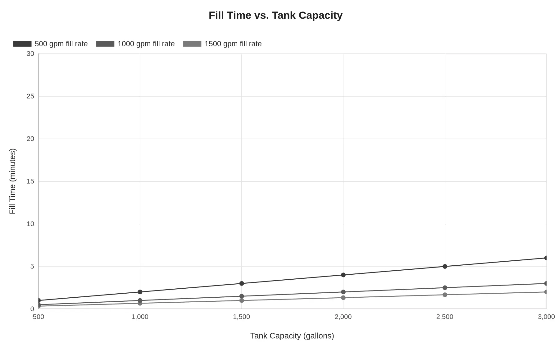
Fill time is tank volume divided by fill rate, so the three curves diverge in straight lines instead of converging. At 500 gallons, a 1,500 gpm source fills in about 20 seconds and a 500 gpm source in about a minute, a spread of roughly 0.7 minutes. At 3,000 gallons it is 2 minutes against 6, a spread of about 4 minutes; 1,000 gpm fills in 3, half the 500 gpm time and a minute behind the 1,500 gpm curve. Those minutes are dead time, since the apparatus sits stationary and off the fireground assignment while its tank refills, and the penalty repeats on every shuttle cycle and every turnaround at a hydrant or dump site. Large tanks only deliver their reserve when the fill source can feed them, whether that is a hydrant-fed water tanker truck with adequate hard suction and a generous dump valve, or a high-volume nurse connection. Otherwise capacity and fill rate should be scaled together rather than increased one at a time.
From Engineering Tradeoffs to a Procurement Sequence
The question that follows all of this is usually the same: which number goes into the bid document first? There is no single figure. Work the sequence and most of the specification writes itself.
Step 1: Mission profile sets the required rate of water delivery
Start with where the apparatus will work. A structural response district with hydrant coverage needs a delivery rate measured in attack-line gallons per minute; a wildland-interface or rural tanker shuttle assignment needs sustained volume at the dump site. That required delivery rate anchors everything else, because it sets the fill rate floor: the apparatus has to replenish at least as fast as it can discharge, or the crew spends the fire waiting at a hydrant or draft site. In any tactical water tender vs municipal pumper evaluation, this one calculation separates the two chassis philosophies faster than any brochure.
Step 2: Terrain and chassis rating set the baffle and tank shape envelope
Once volume and delivery rate are fixed, the operating environment constrains how the water can be carried. Steep grades, unimproved roads, and long off-road approaches load the tank structure differently than flat municipal pavement. Chassis rating, axle loading, and center-of-gravity limits then set practical tank geometry and the tank baffle spacing needed to control slosh-induced dynamic loads. Check the heavy-duty chassis classes and their gross axle ratings before committing to a tank profile.
Step 3: Total cost of ownership arbitrates between configurations
With the envelope defined, two or three viable configurations usually remain, and total cost of ownership breaks the tie: pump and plumbing wear from high-cycle fill operations, baffle and tank inspection intervals, valve and manifold maintenance, downtime, and staffing time lost at the fill site. A higher initial fill rate that removes a second responder trip often pays for itself within a few seasons. Fill-and-transfer accessories deserve the same lifecycle scrutiny as the pump.
Specify the two decisions separately
This is where procurement documents most often go wrong. Close baffle spacing is a structural and handling decision: it governs tank integrity, chassis stress, and how confident a driver feels on a grade. Fill rate is a plumbing and pump decision: intake size, manifold layout, pump capacity, and the transfer hardware behind it. Bundle the two into one performance clause and vendors will trade one against the other to hit a headline number.
Write them as independent line items that can be verified separately. Require baffle spacing and tank structure to be substantiated by structural calculation against the specified chassis rating, and fill rate to be demonstrated at a stated draft lift and hose length. Specified separately, each requirement can be judged on its own merits, and the apparatus that results matches the mission instead of the marketing sheet.
A fill-rate argument is always an argument about a chain of restrictions, and it helps to look at the chain itself. The schematic below strips the apparatus to its hydraulic skeleton so each segment can be audited on its own rather than having everything blamed on the pump curve. Crews comparing compartment layouts and inlet configurations across chassis classes can apply the same reading to water tanker fire truck specifications before a bid is written.
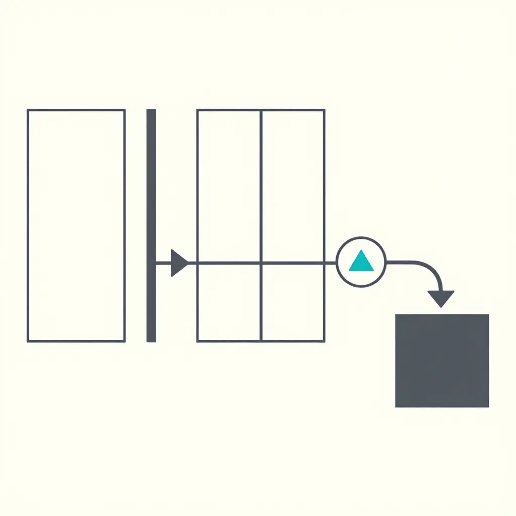
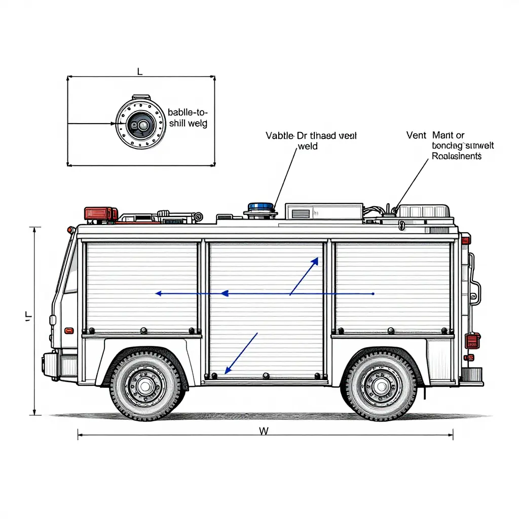
Figure 1. Neutral process illustration identifying every segment along the raw water path where fill-rate losses accumulate.
The diagram traces raw water from the fill source through the fill port, internal piping, and tank compartments, then through the transfer pump to the discharge outlet, isolating each segment where fill-rate losses accumulate.
Read left to right, the diagram is a loss budget. The fill port sets the entry orifice; the internal piping adds friction and bend losses; each compartment boundary adds a transfer restriction; the pump stage either recovers what survives or throttles it further. One undersized element caps the whole chain, however generous the others are.
Frequently Asked Questions: Tank Baffle Spacing and Fill Rate Tradeoffs
Does closer tank baffle spacing always improve safety?
No. Tighter spacing cuts slosh amplitude and the dynamic surge that reaches the chassis frame, but it adds baffle mass, weld seams, and dead volume that trims usable capacity. The right spacing comes out of compartment geometry, design fill level, and the worst braking or grade load, not from a “tighter is better” rule.
Can a municipal pumper be specified with a larger tank?
Yes, within the axle and gross vehicle weight ratings of the chassis. Every additional 1,000 L (about 264 gal) of water adds roughly 1,000 kg (2,205 lb) plus the mass of the reinforced tank shell, so suspension, braking, and pump-drive ratings have to be re-verified. Past roughly 2,000 gal, the technically correct answer is a purpose-built water tanker fire truck on a custom chassis rather than a stretched pumper.
How does fill rate affect tank and piping structural design?
Fill rate sets inlet pipe diameter, valve sizing, and the hydraulic load applied to the shell and baffles. High rates drive the incoming stream against the tank top and produce shock loads, so tanks filled above roughly 1,000 gpm generally need inlet deflectors, internal stiffeners, and oversized venting. Lower rates allow lighter tanks and thinner inlet plumbing, at the cost of longer refill cycles at the water source.
What vent capacity is required to sustain a given fill rate?
The vent has to pass the incoming water volume plus the air it displaces, so free area is sized to keep air velocity at or below fill velocity with minimal pressure rise in the tank. As a practical rule, specify vent free area above the area of the fill connection, then confirm it by measuring tank pressure during a full-rate fill test.
How are baffle spacing and fill rate verified during acceptance testing?
Baffle spacing is confirmed by internal inspection through the access port or manway, comparing the measured baffle count and position against the approved build drawings. Fill rate is confirmed by a timed fill from a calibrated source, measured volume divided by elapsed time, run at rated discharge, with vent pressure and piping movement checked against design limits.
Two Variables, Two Requirements
Baffle spacing is a structural decision. Its influence runs to tank integrity, weight distribution across the chassis, axle loading, and how a loaded vehicle behaves in motion and in transit. Fill rate is an operational variable: it sets the tempo at which a tank returns to service, and it is governed by inlet sizing, plumbing configuration, and available water supply rather than by tank geometry. Each answers a different question, and neither substitutes for the other.
In the tactical water tender vs municipal pumper comparison, that means specifying the two figures independently, against the requirement that actually drives each. One baffle geometry and one fill configuration will not serve both classes, because their constraints diverge at the design stage. Sound apparatus selection treats baffle spacing and fill rate as separate line items with separate justifications, each documented against its own performance requirement.