Auditing a Chinese ARFF Truck Manufacturer: Two Decisive Checkpoints
A factory audit of an ARFF truck manufacturer in China should concentrate on two checkpoints: foam tank welds and axle load margin. These two items, rather than paint finish or cab trim, decide whether the vehicle stays serviceable through sustained full-load airport rescue operations.
The scope is narrow enough to state in two clauses. The first covers weld process control on the foam tank: base material certification, joint preparation and fit-up, welding procedure specification, welder qualification records, non-destructive testing coverage, and post-weld treatment of the tank shell and baffles. The second covers weight-to-rating compliance: verified kerb weight, water and foam concentrate payload, load distribution across each axle in the worst credible case, and the residual margin against the chassis manufacturer’s rated axle loads and tyre limits.
This is written for the people who sign off on the purchase: airport fire departments, ARFF procurement and engineering teams, international distributors, and quality or sourcing auditors who have to document their findings in a defensible form. It assumes you are comparing several candidate airport fire trucks and need a repeatable basis for scoring them, not a general impression from a site visit.
What follows supplies the inspection criteria, the documents to request from the supplier, and the calculation that scores a supplier against both checkpoints. Treat the two clauses as one test: a tank that weeps under vibration and a chassis that is already overloaded at delivery fail the same acceptance question – whether the truck can run a full shift at an airport and come back for the next one.
Foam Tank Weld Audit: Joint Design, Process Control and NDT Coverage
Foam tank welds sit at the intersection of pressure retention, corrosion resistance and vehicle durability, which is why they are audited as a discrete scope rather than folded into a general fabrication check. An ARFF foam tank on an airport fire truck is a baffled, compartmented vessel that sees static head loads, braking and cornering slosh forces, and permanent contact with foam concentrate on one face and atmospheric moisture on the other. The audit therefore tests three things in sequence: whether the material selection matches the service environment, whether the joint design and welding process are capable of producing that joint repeatably, and whether NDT coverage is dense enough to prove it weld by weld.
1. Base material specification: shell, baffles and compartment dividers
Auditors should begin with mill certificates (EN 10204 3.1 as a minimum) cross-checked against the drawing’s material callout and heat-number traceability to the physical plate.
- Stainless steel 304 / 304L is acceptable for tanks serving potable-grade water or non-aggressive foam concentrates in temperate climates, where chloride exposure during service and washdown remains low.
- 316L is the defensible choice where concentrates carry higher chloride loadings, where sea-water-capable ARFF operations are specified, or where washdown water quality is uncontrolled. The molybdenum addition raises resistance to pitting and crevice attack at weld heat-affected zones, which are the first sites to show it.
- Carbon steel with internal coating is used where weight and cost dominate and the coating system is correctly qualified. Audit points here are coating thickness (DFT) records, holiday testing of the applied film, stripe coating of weld toes and fillets, and cure records. A coated tank without coated weld toes is a coating failure waiting to happen.
Corrosion rationale for foam concentrate service: AFFF, fluorine-free and protein-based concentrates contain salts, glycols, surfactants and inhibitor packages that behave differently from water, and dilution with local water supplies introduces chlorides and hardness. Internal surfaces must therefore resist both the concentrate and its diluted working solution, and the audit should confirm that the material selection report names the specific concentrate family and dilution ratio assumed.
2. Joint configurations requiring audit attention
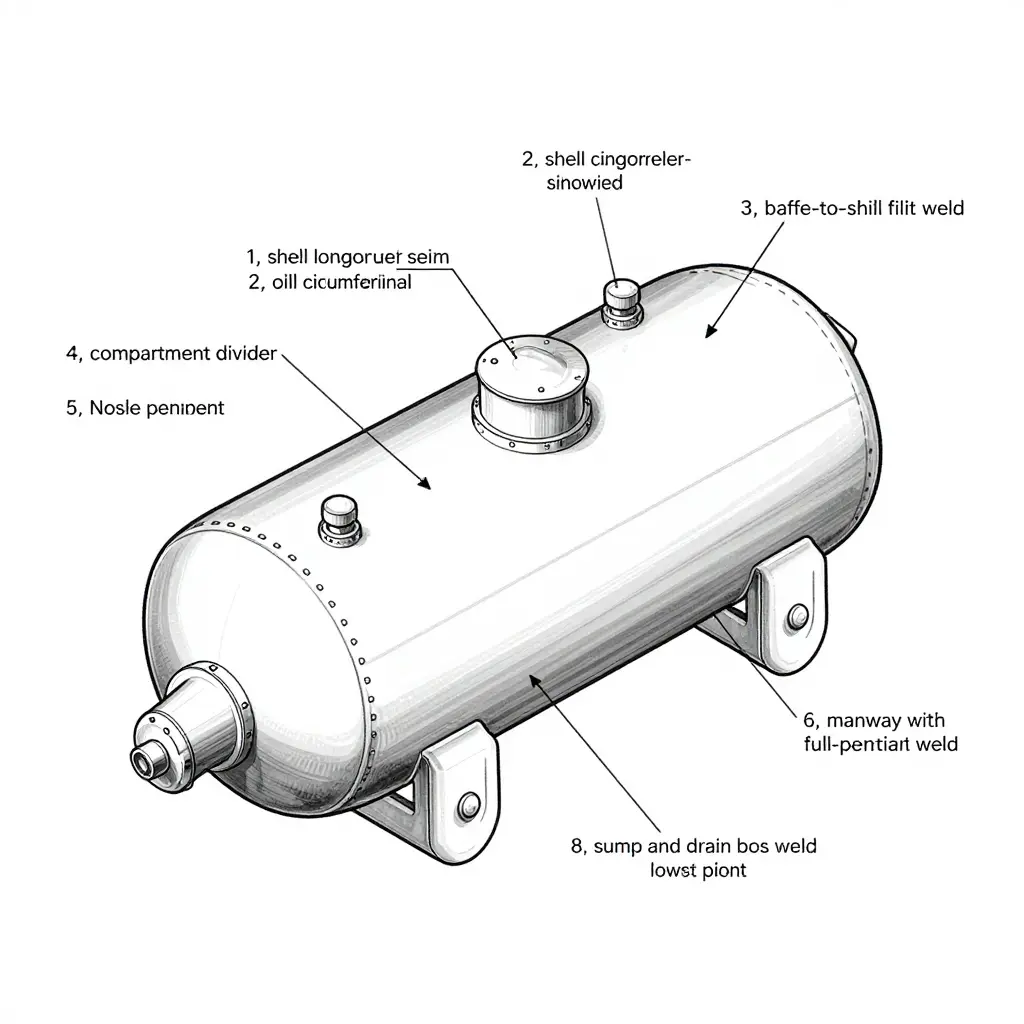
- Shell longitudinal seams. Usually submerged arc or GTAW with filler; check bevel preparation, root gap consistency, fit-up record and whether the seam is full penetration with a verified root.
- Shell circumferential seams. Higher restraint and greater misalignment risk; check alignment tolerance, temporary attachment removal, and whether tack welds were consumed into the final weld or ground out.
- Baffle-to-shell fillet welds. These carry slosh loads and are the most common source of service leaks. Audit leg length against drawing, continuity around openings, and whether the fillet is specified on both sides of the baffle.
- Nozzle and manway penetrations. Expect reinforcement pads or full-penetration welds with documented root condition. Check weld neck thickness, reinforcement geometry and post-weld cleaning that does not smear iron onto stainless surfaces.
- Sump and drain boss welds. Located at the lowest point and opposite the fill, these are simultaneously the hardest to weld and the hardest to inspect. Verify accessibility for welding and weld inspection, and confirm full penetration or double-sided access rather than a single external fillet.
3. Welding process documentation on the shop floor
The documents must be at the workstation, not only in the quality office:
- WPS per ISO 15609 or ASME Section IX, matched to each joint type and thickness range actually in production.
- PQR supporting each WPS, with mechanical test results traceable to the qualification assembly.
- Welder qualification records per ISO 9606-1 or ASME IX, listing process, position, thickness and validity date, plus the welder ID stamp that matches the stamp on the tank.
- Consumable storage and issue control: sealed filler wire, heated quivers or ovens for electrodes, issue-and-return logs, and evidence of stainless-only brushes, grinding discs and handling to prevent iron contamination.
4. NDT coverage
The audit maps NDT method to joint category, then confirms personnel certification (ISO 9712 Level II or equivalent) and equipment calibration status.
| Joint category | Method | Typical coverage | Record expected |
|---|---|---|---|
| All welds | Visual (VT) | 100% before and after cleaning | Inspector sign-off, joint map |
| Fillet welds (baffles, pads, bosses) | Dye penetrant (PT) | 100% of accessible fillets | PT report, acceptance criteria |
| Full-penetration butt welds (shell, manway) | UT phased array or RT | 100% of critical seams, or project-specified sampling | Scans/radiographs, defect disposition |
| Assembled tank | Hydrostatic + leak test | Per design pressure, defined hold time | Pressure chart, leak log, repair record |
For NDT planning, sampling percentages should be written into the purchase specification rather than left to the manufacturer’s discretion, and repair rates should be tracked as a process indicator: a rising repair rate on circumferential seams points to fit-up problems upstream, not to welder skill alone.
Four weld features an auditor must physically verify
- Weld toe profile – smooth transition, no deep notches at the cap-to-base metal junction; check at representative locations with a profile gauge.
- Undercut depth – measured against the acceptance criteria in the specification, on both shell seams and baffle fillets.
- Spatter removal – no adherent spatter or arc strikes on internal surfaces, particularly where coating or passive film integrity matters.
- Baffle weld continuity – full perimeter continuity around each baffle, including at openings and internal corners, with no skipped segments left as drainage gaps.
Taken together, these checks let procurement teams compare fabrication quality across candidate suppliers of airport fire trucks before the chassis and axle-load review begins. Sample the weld records, NDT reports and physical checks on the same visit, so that paper coverage can be reconciled against what is actually on the tank.
The matrix below is the sampling plan for that verification. Pick joints at random from the weld map and watch the test happen rather than reviewing a finished dossier in the conference room; it is meant to be carried onto the foam fire truck fabrication line, clipboard in hand, during the audit window.
Foam Tank Weld Inspection and Acceptance Matrix for ARFF Truck Factory Audits
| Inspection Item | Test Method or Reference Standard | Acceptance Criterion | Sampling Rate | Record to Be Retained |
|---|---|---|---|---|
| Visual examination of all shell, baffle, and head welds | VT by qualified inspector to ISO 17637 or ASME BPVC Section V Article 9, after cleaning and before coating | Full weld length free of surface porosity, cracks, lack of fusion, undercut beyond specified limit, and weld spatter; reinforcement within drawing tolerance | 100% of accessible welds, both before and after internal coating | Signed VT report with joint numbers, inspector ID, date, and photographic evidence of any repaired area |
| Dye penetrant testing of fillet welds (baffles, baffle-to-shell, nozzle reinforcement) | PT to ASTM E165 or ISO 3452-1, solvent-removable or water-washable method, dwell and development times per procedure | No linear indications; rounded indications below the size and density limits of the cited acceptance code; complete post-test cleaning confirmed | Minimum 10% of fillet weld length per tank, including 100% of baffle-to-shell joints in the first tank of each production batch | PT procedure, penetrant and developer batch numbers, operator certification level, indication map, and acceptance sign-off |
| Ultrasonic testing of butt welds | UT to ISO 17640 or ASTM E164, straight-beam and angle-beam as specified, calibration on reference block before each session | No indications exceeding the recording and acceptance limits of the cited code; full root penetration and fusion verified on double-welded joints | 100% of longitudinal and circumferential butt welds on the shell and dished ends | UT report with scan coverage sketch, calibration block ID, equipment serial number, and operator qualification certificate |
| Radiographic testing where specified | RT to ISO 17636-1 or ASTM E94, film or digital detector, IQI sensitivity per contract | Weld quality level per the contractual radiography class; no cracks, incomplete penetration, or elongated slag inclusions beyond the stated limit | As specified by contract, typically 10-20% of butt weld length or 100% of T-joints and nozzle-to-shell welds on critical tanks | Radiographs or digital image files, IQI readings, exposure technique sheet, and interpretation report by a certified Level II or III reader |
| Weld map and joint numbering | Manufacturer’s weld map drawing cross-referenced to plate layout, nozzle schedule, and welder ID | Every production weld carries a unique, permanently marked joint number traceable to the as-built drawing and to the inspection record set | 100% coverage of structural and containment welds on each tank | As-built weld map with revision status, joint numbering legend, and permanent marking method |
| Welder qualification traceability | Welder performance qualification to ISO 9606-1 or ASME BPVC Section IX, position and thickness range matched to production joints | Each welder qualified for the process, position, and material thickness actually welded; qualification valid and within its renewal period | 100% of welders active on the order, with certificates verified against the weld map log | Welder qualification certificates, continuity log, and welder ID stamped or recorded against each joint number |
| Hydrostatic pressure test | Hydrostatic test to the manufacturer’s cited pressure vessel or tank standard, using calibrated gauges and deionized or filtered water | No leakage, seepage, or permanent deformation at the specified test pressure held for the specified duration; test pressure not less than the factor of design pressure required by the cited standard | 100% of completed foam tanks, per unit, before internal coating and final assembly | Calibrated gauge certificates, pressure-time chart or logged readings, water quality note, ambient and water temperature, and witness signature |
| Internal coating integrity for carbon steel tanks | Holiday (spark) test to NACE SP0188 or equivalent, plus dry film thickness survey to SSPC-PA2 | Zero holidays at the specified test voltage; DFT within the specified range with no reading below the minimum; stripe coats intact at welds and edges | Holiday test on 100% of coated internal surfaces; DFT survey at a minimum of five readings per square metre and one per weld seam | Coating product data sheet, batch number, DFT survey grid, holiday test voltage and results, and applicator record |
| Fit-up and edge preparation check | Dimensional inspection of joint geometry, root gap, bevel angle, and alignment against the approved welding procedure specification | Gap, bevel, misalignment, and peening condition within WPS limits; no tack welds left un-fused in the finished joint | First article plus random check on at least 20% of joints per shift | Fit-up inspection sheet signed by the fitter and inspector, tied to joint numbers |
Acceptance criteria listed above are indicative and must be confirmed against the contractual technical specification and the applicable pressure vessel or tank standard cited by the manufacturer, since a tank built to a national code, a UN transport standard, or a customer-specific specification will carry different limits and test factors.
Deviations are to be recorded on a numbered nonconformance report cross-referenced to the joint number and weld map entry, then closed only through a documented repair, re-test, and re-inspection sequence signed by the quality manager before the tank proceeds to coating.
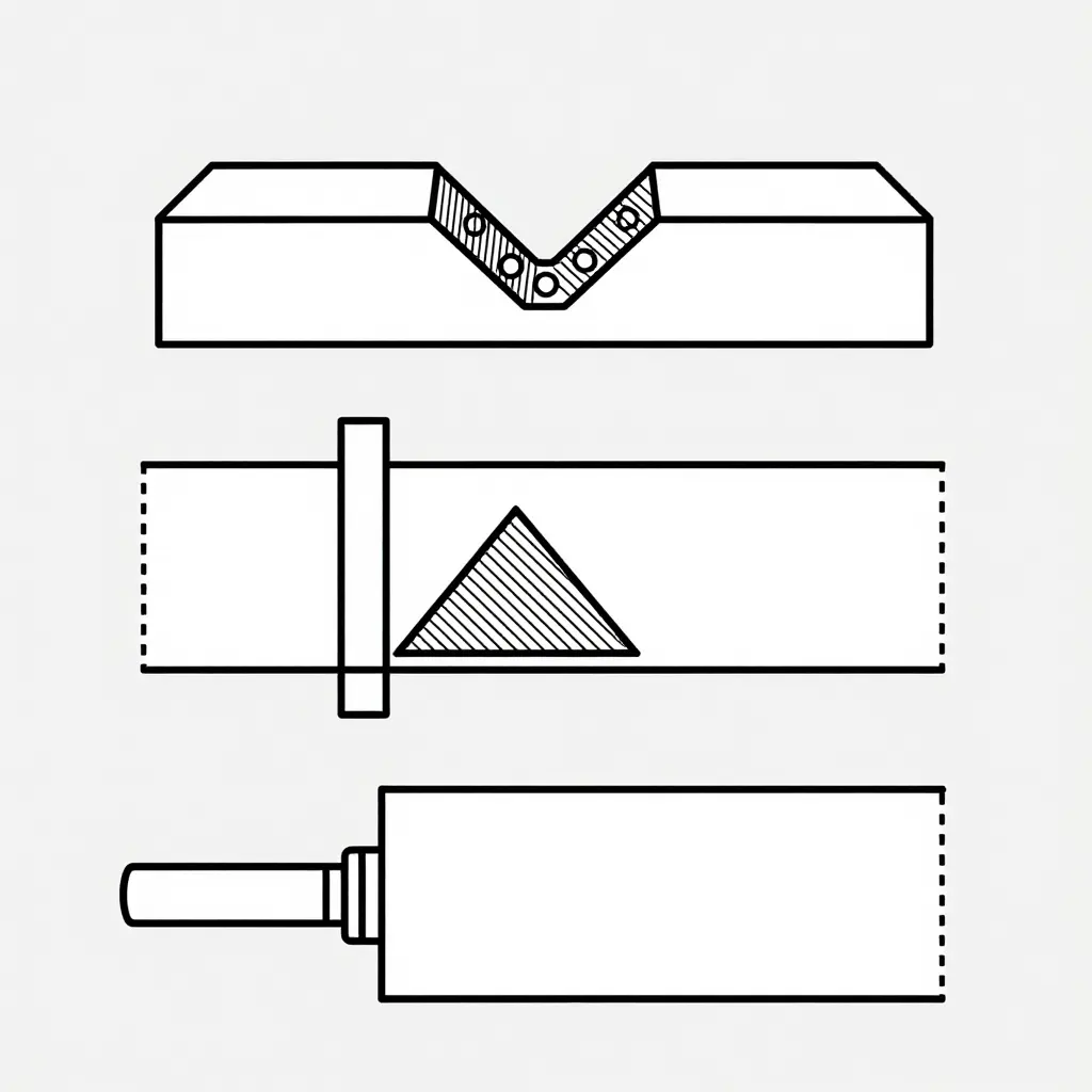
Three joint details an auditor will physically locate on the tank before accepting any NDT report: the longitudinal and circumferential butt seams, the baffle-to-shell fillet, and the nozzle penetration at every foam and water connection. Hatched areas mark weld metal; dashed outlines mark the volumetric inspection zone that UT, RT, or phased-array coverage must reach.
Documentation and Traceability: Turning Weld Quality into Evidence
A foam tank that looks immaculate under a flashlight proves very little on its own. In a factory audit, a good weld is only as convincing as the paper trail behind it, because that trail is what lets an airport fire department sign off the vehicle years later or defend the purchase to a funding authority. In an ARFF truck manufacturer in China, the documentation package is where traceability holds or collapses: every joint on the tank shell, baffle and bulkhead should be resolvable from the steel mill certificate through to the signed test record.
What the Audit Must Retrieve
A credible vendor should hand over the full welding dossier without stalling, without “we will send it next week”, and without gaps. Retrieve and sample-check these yourself:
- Welding procedure specifications (WPS) and supporting procedure qualification records (PQR) for each material grade and thickness range used on the tank, stamped and approved.
- Welder qualification certificates checked against valid ranges – process, position, material group, thickness and expiry date. A welder qualified for 6 mm flat-position work is not automatically qualified for a 12 mm vertical baffle joint.
- Material certificates to EN 10204 3.1 or an equivalent standard, matched to the heat numbers actually stamped on the plate.
- A numbered weld map that assigns a unique identity to every joint and links it to its specific NDT report – not a generic “tank radiographed, passed” statement.
- NDT operator certification, with the Level II (or equivalent) competence and method scope for the technique used, whether RT, UT, PT or MT.
- Hydrostatic test logs recording test pressure, hold time, ambient and water conditions, and the inspector’s signature and date.
- Third-party or classification-society witness reports wherever the procurement contract demands independent witnessing.
How the Package Should Read
| Document | What the auditor is actually testing | Typical weak point |
|---|---|---|
| WPS / PQR | Whether qualified procedures exist for the exact joint and thickness | Generic procedures copied from a supplier catalogue |
| Welder certificates | Whether the person who welded is qualified for that joint | Expired certificates or missing position coverage |
| EN 10204 3.1 mill certificates | Whether the plate is what the design assumed | Heat numbers that do not match the physical plate |
| Numbered weld map + NDT reports | Whether every joint has been accounted for | Joint numbering that skips baffle-to-shell fillets |
| Hydrostatic logs | Whether leak integrity was demonstrated, not assumed | Missing hold time or unsigned entries |
Before a Weld Is Accepted: Cross-Check These Three
Documents can be individually flawless and still contradict each other. The audit should force the following comparisons:
- The numbered weld map must agree with the NDT report on joint ID, joint type and location – one joint missing from the NDT set is a non-conformance, not a clerical slip.
- The NDT report must agree with the welding procedure specification on the process and consumable specified for that joint, so the tested weld is the weld the procedure intended.
- The weld map must agree with the material and welder records, so the heat number and the qualifier behind each joint can be identified by name, not by assumption.
- The delivered package must satisfy the contract’s archive period and language requirements – typically a long retention obligation for the tank and pressure-retaining records, supplied in the buyer’s contractual language plus English, in both signed hard copy and searchable digital form.
One point that surprises first-time buyers: documentation completeness is scored independently from weld workmanship during the audit. A tanker with beautiful, uniform beads can still lose points on the documentation line if the weld map is incomplete or the mill certificates are unreadable. Treat the dossier as a deliverable in its own right, specify it in the purchase order, and review it at the pre-shipment stage – then compare it against the actual foam tank build where the plate is cut, formed and welded. For teams putting together the technical annex, it also helps to see how a finished unit is configured in practice; a look at the foam fire truck range gives a useful reference for the joints and compartments that the weld map must cover.
Axle Load Margin: Definitions, Calculation and Audit Benchmarks
Before an auditor can sign off on a foam tank weld or a chassis conversion, everyone in the room needs the same vocabulary for weight. On an ARFF truck the numbers do not sit still: a few hundred litres of extra foam concentrate, a heavier pump set, or a relocated monitor can shift the load balance enough to invalidate a compliance claim. Start with the definitions.
- Gross vehicle weight rating (GVWR) – the maximum total mass the completed vehicle is rated to carry, comprising kerb weight plus all payload, crew, and equipment.
- Front and rear gross axle weight ratings (FGAWR / RGAWR) – the maximum mass each axle assembly is rated to carry, distributed across its tyres, springs, and brakes.
- Kerb weight – the vehicle as delivered with full coolant, lubricants, fuel, and standard on-board equipment, but without water, foam concentrate, or crew.
- Fluid payload – the combined mass of water and foam concentrate. Water is taken as 1.00 kg/L; concentrate is denser and typically falls between 1.05 and 1.15 kg/L depending on formulation, so a 1,000 L concentrate tank at 1.10 kg/L adds roughly 1,100 kg. Auditors should ask for the actual density certificate rather than accept a round-number assumption.
- Crew and equipment allowance – a declared mass for occupied seats, PPE, hand tools, hose, and loose equipment, normally 90-100 kg per crew member plus a documented equipment allowance.
The margin formula
Axle load margin (%) = [(Rated axle capacity – audited axle load at full payload) / rated axle capacity] x 100
A negative result is an overload; a positive result is headroom. Calculate it separately for the front axle and the rear axle, using a weighed vehicle at full fluid payload, full crew and full equipment – not an estimate built from catalogue figures.
Why ARFF payloads are unusually high
Airport rescue vehicles are sized around application rate and duration. A runway incident may demand tens of thousands of litres of water and foam delivered at high flow before municipal supply reaches the scene, so a large share of the vehicle’s mass sits in the tanks, the fluid they hold and the pump that moves it. That concentration of weight makes tank placement, baffle design and fill sequence decisive for the final balance.
Why both axles need a positive margin
An aggregate GVWR check can hide a rear axle that is over its rating while the front axle is running light – the total looks fine and the vehicle is still unsafe. Rear overload degrades service brake performance, tyre casing life, suspension travel, and stability; front overload compromises steering authority and tyre loading. Per-axle limits are also what regulators, bridge formulas, and road authorities actually enforce. Reviewing heavy-duty fire truck platforms alongside their published chassis ratings helps confirm that declared figures match the class of vehicle being audited.
Audit benchmark band
For most ARFF procurement audits, a positive axle load margin of 5-10% on each axle at full payload is a defensible working benchmark. A purchaser writing the specification can set the floor higher – the FAQ at the end of this paper argues for 10% on each rated GAWR and 5% on gross weight – and should confirm whichever figure it chooses against the chassis manufacturer’s limits, since some builders require a fixed derating for fire apparatus and others impose a hard conversion cap. Finally, require the tyre load index, brake rating and suspension rating to be consistent with the declared axle ratings; a 13,200 kg rated axle running on tyres rated lower does not deliver real margin, only a paperwork margin.
Visualising the Margin: Where the Kilograms Actually Sit
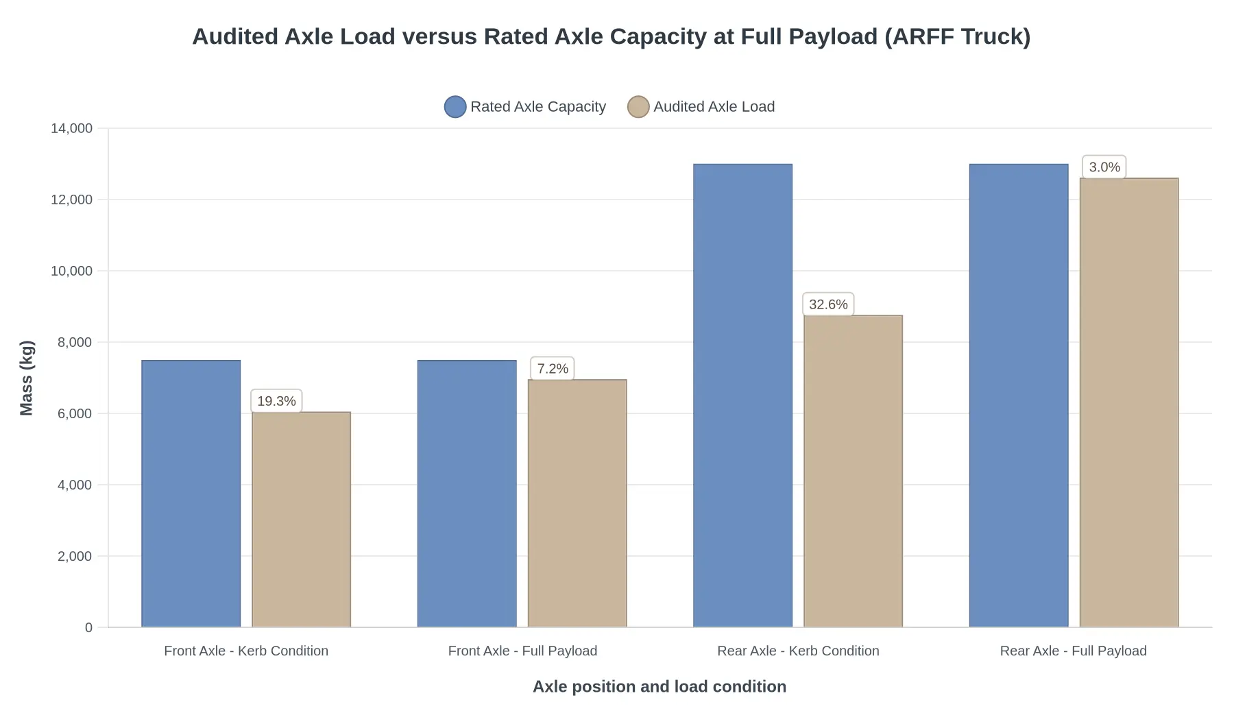
Numbers on a calculation sheet are easy to argue with; a chart is not. The grouped bars below plot the weighed axle loads of a representative 6×6 ARFF truck against the rated capacity of each axle, at kerb condition and again at full payload with foam tank and water tank topped off. Rated capacity is shown in muted steel blue, audited load in sand grey, and the remaining margin percentage is annotated above each audited bar.
Exact values used in the chart (kilograms):
- Front Axle – Kerb Condition: rated 7,500 kg; audited 6,050 kg; remaining margin 19.3% (1,450 kg)
- Front Axle – Full Payload: rated 7,500 kg; audited 6,960 kg; remaining margin 7.2% (540 kg)
- Rear Axle – Kerb Condition: rated 13,000 kg; audited 8,760 kg; remaining margin 32.6% (4,240 kg)
- Rear Axle – Full Payload: rated 13,000 kg; audited 12,610 kg; remaining margin 3.0% (390 kg)
Figure: Audited axle load versus rated axle capacity at kerb and full payload for a representative 6×6 airport rescue and fire fighting chassis, with remaining margin percentage annotated above each audited bar. The Rear Axle – Full Payload category carries the smallest margin at just 3.0% (390 kg), because the foam tank, water tank and pump module sit directly over the rear bogie, so every litre added at full payload lands on that single rating. That is below the 5-10% band recommended above, which is the finding such a chart exists to expose: put the weighing, foam density verification and baffle inspection on the rear axle at full payload, where a small density or distribution error is enough to consume the entire reserve.
If you are benchmarking axle ratings across chassis families, it helps to compare the specification sheets of several airport fire trucks side by side before you commit to a factory audit plan.
Axle Load Margin Verification Sequence
At every step below, the auditor should request documentary evidence rather than verbal assurance: signed weighbridge tickets, current calibration certificates, tank capacity drawings, foam concentrate specification sheets, the payload distribution calculation, and the manufacturer’s declared gross axle weight rating plates. A complete and internally consistent paper trail is what separates a defensible ARFF procurement file from a marketing brochure, and it is the only basis on which an airport fire truck should be accepted for delivery.
- Obtain the weighbridge certificate for the kerb-condition vehicle. Request the original ticket showing the apparatus weighed as delivered – fuel, coolant and lubricants at their kerb-condition levels, tanks empty – including date, scale ID and operator signature.
- Verify the weighing equipment calibration status. Confirm the scale’s calibration certificate is current, traceable to a national standard, and valid within the acceptable interval at the time of weighing.
- Confirm tank compartment volumes and foam concentrate density used in the payload calculation. Ask for the as-built tank drawings and the foam concentrate data sheet, then check that the density value in the calculation matches the product actually supplied.
- Compute total fluid payload at 100 percent fill. Independently recalculate water plus foam concentrate mass from the confirmed volumes and densities, and compare it with the figure claimed in the specification.
- Confirm how the design distributes that payload between axles. Request the weight distribution study or calculation note showing the centre of gravity and the share of fluid load assumed to act on each axle group.
- Compare the resulting axle loads against the declared ratings. Check each calculated load, including any allowance for crew and equipment, against the rated capacity on the manufacturer’s plate and the chassis documentation.
- Calculate the margin percentage for each axle. Express remaining capacity as a percentage of the rated value so the axle load margin can be assessed consistently across axles and across competing bids.
- Review tyre load index, brake rating and suspension documentation against those loads. Confirm that tires, brakes and springs are rated for the verified loads, including the front axle’s steering-axle limits.
The verification sequence constitutes a pass only when every axle’s calculated load at 100 percent fill remains below its declared gross axle weight rating, with a positive margin that is documented, independently recalculated and formally accepted by the buyer.
Reading Load Distribution and Axle Margin at a Glance
Axle load margin is one number that tells a reviewer whether a foam-filled ARFF truck still has lawful, safe reserve left on each axle. The schematic below reduces the whole verification to two ideas: how the body weight actually divides between the front and rear axle, and how much of the rated capacity is still unused once the truck is weighed at full operating condition – water, foam concentrate, fuel, crew and equipment all on board.

How to Read the Diagram
- The rectangle is the superstructure and tank package, not the chassis outline. Its position over the axles is what a procurement reviewer should question first, because a foam tank mounted too far rearward shifts load onto the axle that is already the legal constraint.
- The two circles are the axles. Their horizontal spacing defines the wheelbase, and every metre of wheelbase change alters the split far more than most buyers expect.
- The arrows are the share of total weight carried by each axle. Unequal arrow length is normal and expected on a two-axle ARFF unit; equal arrows are almost always a sign of a drafting error or a deliberately front-loaded design.
- The bar pair on the right is the margin check. The taller bar is rated capacity, the shorter bar is the measured load, and the hatched area between them is the only legitimate reserve.
The Margin Computation in Plain Terms
Margin is subtraction, but it is subtraction done twice – once per axle – and the result must be positive on both.
| Term | What it represents | Where auditors obtain it |
|---|---|---|
| GAWR-F / GAWR-R | Front and rear axle rated capacity | Axle data plate, OEM certificate, or approved drawing |
| L-F / L-R | Measured load on each axle at full operating condition | Certified weighbridge printout, per axle |
| M-F = GAWR-F – L-F | Remaining front axle margin | Calculated from the two figures above |
| M-R = GAWR-R – L-R | Remaining rear axle margin | Calculated from the two figures above |
| Governing margin | The smaller of M-F and M-R | This single value governs the whole approval |
A design that reports only total gross weight, without per-axle figures, cannot demonstrate margin at all. Ask for the per-axle weigh ticket, and ask that it be taken with the foam tank filled to its rated volume rather than dry – the filled condition is where the margin narrows. When the governing margin is thin, the remediation is usually geometry rather than hardware: repositioning the tank, moving the pump set, or resizing the foam concentrate tank. Reviewing comparable airport fire trucks with different tank layouts makes those trade-offs easier to see before a contract is signed.
Both the hatched margin zone and the arrow lengths should stay stable across the audit documents – drawing, calculation sheet and weigh ticket. Any mismatch between the three is the signal that triggers the non-conformance review that follows.
Non-Conformance Handling and Re-Inspection Protocol
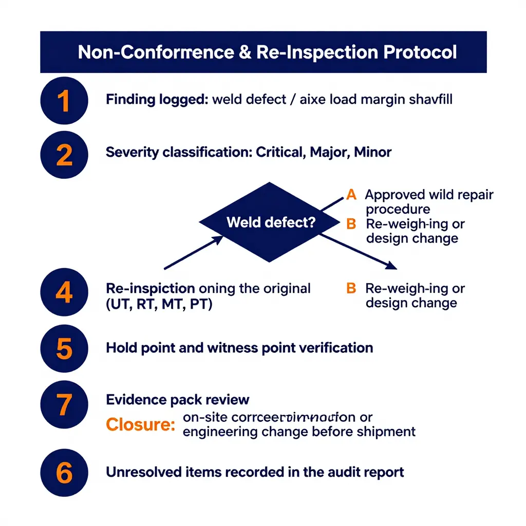
A factory audit only has value if it produces a defensible response to what it uncovers. In an ARFF truck program, the two focal areas – stainless steel foam tank welds and axle load margin – behave very differently under scrutiny, and the protocol below sets out how an auditor should log, grade, disposition and close findings in each. The governing principle is simple: nothing is released on verbal assurance, and no non-conformance is closed without traceable evidence.
Classifying non-conformances by severity
Every finding should be graded before any repair is discussed, because severity determines who must approve the disposition. Weld defects and margin shortfalls use separate technical criteria but share the same three-tier scale.
| Severity | Weld defects (foam tank, piping, brackets) | Axle load margin shortfall | Release impact |
|---|---|---|---|
| Critical | Lack of fusion, cracking, incomplete penetration on a pressure-retaining or tank shell joint; porosity or slag exceeding the acceptance level of the applicable standard | Margin below the contractually specified minimum, or any axle exceeding its rated capacity at full foam and water load | Hold – vehicle cannot be released; design change or re-weighing required |
| Major | Undercut, misalignment, incomplete weld length, or weld profile defects outside acceptance criteria but not affecting structural integrity | Margin consumed beyond the tolerance allowed for build variance, still above the contract minimum | Hold – corrective action and re-inspection required before release |
| Minor | Cosmetic irregularities, spatter, weld dressing defects, marking or documentation errors | Recorded weight variance without breaching the margin threshold | May be closed on site with documented verification |
An auditor should confirm that the manufacturer’s own inspection records apply the same grading, and that no finding was downgraded after detection in order to bypass a design review.
Weld repair and mandatory re-inspection
Any weld repair must be covered by an approved repair procedure – typically a qualified welding procedure specification (WPS) with a supporting procedure qualification record, plus a defined excavation and preparation method. Field patching or unqualified touch-up welding is a reportable non-conformance in itself.
Re-inspection must use the same NDT method that originally detected the defect. A crack found by ultrasonic testing is re-examined by ultrasonic testing after excavation and repair; a defect found by radiographic testing is re-radiographed; dye penetrant and magnetic particle findings are re-tested by the same technique. Substituting a visual check for the original method does not close the item. Where the repair removes material or changes geometry, the auditor should also confirm post-repair dimensional checks and, for tank shell work, a repeat hydrostatic or leak test at the specified pressure.
Hold points and witness points to confirm before release
Walk the inspection and test plan and verify that each hold point was formally signed off – not merely completed – and that witness points were either attended or waived in writing by the purchaser’s representative.
| Reference | Stage | Type | Evidence expected |
|---|---|---|---|
| HP-01 | Weld procedure and welder qualification approval | Hold | Approved WPS/PQR, valid welder certificates |
| WP-01 | Tank shell fit-up, before welding | Witness | Fit-up and dimensional record, photographs |
| HP-02 | NDT of shell and baffle welds | Hold | NDT report, technician certification, acceptance criteria |
| HP-03 | Weld repair and re-inspection after any rejection | Hold | Repair procedure, excavation record, repeat NDT report |
| WP-02 | Hydrostatic or leak test of foam tank | Witness | Pressure and hold-time record, signed test certificate |
| HP-04 | Axle load calculation and physical weighing | Hold | Weight ticket per axle, calculation sheet, margin statement |
| HP-05 | Pre-shipment final inspection and documentation pack | Hold | Complete evidence file, release note |
Evidence required to close an item
Closure is an evidence question, not an opinion. Each non-conformance should carry a record set comprising: the original finding with location, date and detecting method; the severity grading and named approver; the disposition (repair, rework, concession, design change); objective proof of completion, such as NDT reports, weighing tickets, revised drawings or engineering change notices; and verification that the corrected item was re-inspected against the same acceptance criteria. Photographs with identifiable location markers are useful supporting evidence but never substitute for test data.
On-site closure versus design change or re-weighing
Corrective actions that stay within the approved design can close on site: weld dressing, re-welding to the qualified procedure with repeat NDT, re-torquing, harness or bracket rework, label and documentation corrections, and minor cosmetic finishing. These require the manufacturer’s quality signature and an updated evidence file.
Items that alter structure, geometry or mass distribution cannot. A margin shortfall driven by the foam tank, pump package or equipment layout requires an engineering change – revised weight and centre-of-gravity calculations, structural review of the affected mountings, and in most programs a physical re-weighing before shipment. The auditor should confirm the revised calculation is issued by a competent engineer, approved through the manufacturer’s design control process, and reflected in the as-built documentation. Until the re-weighing record exists, the item remains open regardless of how small the projected correction appears. Buyers evaluating foam fire truck platforms should treat this evidence chain as a primary selection criterion rather than an afterthought.
Any non-conformance that remains unresolved at the close-out meeting should be recorded in the audit report as an open finding with its severity, responsible function, required corrective action and target date, and should block shipment release until formally closed.
Frequently Asked Questions on ARFF Truck Factory Audits
Procurement teams auditing an ARFF truck manufacturer in China usually raise the same technical points late in the process: which weld tests are mandatory, how much load headroom is acceptable, and what evidence survives delivery. The answers below are written for audit checklists and contract annexes rather than marketing review. For a comparison of platform configurations before scheduling a site visit, review the airport fire truck range first.
Which non-destructive testing methods are required for foam tank welds, and who certifies the operators?
Visual inspection to ISO 17637 is mandatory on all seams, followed by penetrant testing to ISO 3452 or ASTM E165 on fillet welds and accessible root passes. Full-penetration butt seams on the tank shell and baffle-to-shell joints typically require radiographic testing to ISO 17636 or ultrasonic testing to ISO 17640. Operators must hold Level II certification under ISO 9712 or ASNT SNT-TC-1A, and the factory audit should verify certificate scope, expiry date, and employer authorization for each technician who signed a report.
What axle load margin should a purchaser require at full fluid payload?
Specify a minimum 10 percent margin against rated front and rear GAWR and 5 percent against GVW, calculated at full foam and water payload plus crew and equipment. Aviation-grade chassis with high foam capacity often warrant 15 percent on the rear axle to absorb hose, monitor, and pump loads. The margin must be proven by a weighbridge ticket per axle, not by a theoretical calculation sheet, and the calculation should be an explicit appendix to the purchase specification.
How is foam tank capacity verified during an audit?
Capacity is confirmed by volumetric fill calibration: metered water is introduced through a calibrated flow meter while levels are marked, then the derived volume is compared with the nameplate figure. Take internal dimensional measurements as well, and confirm baffle spacing and position against the approved drawing. Discrepancies above roughly 2 percent between calculated and nameplate volume require written justification before the unit is accepted.
Which documents must be reviewed to confirm weld traceability?
Request the WPS and supporting PQR qualified to ISO 15614 or ASME Section IX, welder qualification records to ISO 9606, and material mill certificates carrying heat numbers. The weld map must assign a unique joint ID to every seam, cross-referenced to NDT reports, operator names, and repair records. During a factory audit, sample at least 10 percent of joints and trace each one from tank plate heat number through to the signed NDT acceptance report.
Can a purchaser appoint a third-party inspector to witness NDT and weighing?
Yes. The contract should define hold points that allow the purchaser’s representative or an independent body such as SGS, TUV, or Bureau Veritas to witness NDT, hydrostatic or pneumatic testing, and weighbridge weighing. Specify notification lead time, typically 5 to 10 working days, along with acceptable report formats and the inspector’s authority to reject non-conforming work. Without an explicit hold-point clause, witnessing rights are difficult to enforce after fabrication begins.
How long should the ARFF truck manufacturer retain weld and weight records for a delivered truck?
Require retention of weld records, NDT reports, and axle weight certificates for the service life of the vehicle, with a contractual floor of 10 years. Records should be delivered as indexed PDF copies at handover so the purchaser is not dependent on the supplier’s archive. Because retention periods vary between Chinese manufacturers, state the requirement explicitly in the quality annex and confirm it during the factory audit.
Scoring Suppliers on Weld Quality and Load Margin
The audit evidence gathered in the preceding sections only becomes a procurement decision once it is weighted. Weld procedure qualification records, radiographic and penetrant results on foam tank shells, baffle and partition welds, dimensional checks, and axle load calculations each speak to a different risk, so the scoring should keep them separate before combining them into a single figure. The weighting below is calibrated for ARFF aircraft rescue fire fighting chassis, where tank integrity and rollover stability carry equal consequence.
| Scoring block | Evidence source | Weight |
|---|---|---|
| Weld integrity | WPQ records, NDT reports, repair and re-test logs, coupon results | 35% |
| Documentation and process control | Traceability of plate and filler lot numbers, ITP sign-offs, calibration records, revision control | 20% |
| Axle load margin | Weighed axle loads against rated GAWR, per-axle and per-tyre margin at full foam and water load | 30% |
| Rating consistency | Declared GVW, pump and foam ratings versus measured values and nameplate data | 15% |
The split is deliberate: 55% of the score sits on weld integrity and documentation, 45% on axle load margin and rating consistency. A supplier that welds well but cannot prove it, or that presents an attractive brochure axle rating without a per-axle calculation at full payload, is not a supplier with a lower score – it is a supplier with an unverified claim. For airport fire trucks, the load margin block should be scored on the measured worst case, meaning every tank full, crew and hose load aboard, and the margin expressed as a percentage of rated axle capacity.
A composite score below 75 out of 100 should remove a supplier from the tender shortlist. Two findings override the composite figure entirely and trigger exclusion regardless of the total: any critical weld without a qualified procedure and recorded NDT, and any negative margin on a single axle at full load. Both are binary pass-or-fail items, not deductions.
One further point belongs in the commercial evaluation rather than the technical one. A manufacturer operating an auditable process control system – documented ITPs, calibrated equipment, controlled weld revisions, and retained inspection records – lowers the purchaser’s verification cost across the vehicle lifecycle. Re-audits become sampling exercises instead of re-inspections, warranty disputes can be resolved against original evidence, and replacement tank sections or weld-affected spares can be sourced against known specifications through fire truck parts channels without re-engineering the repair.
The company behind this assessment is an established manufacturer of firefighting and rescue equipment operating across multiple markets, and the scoring framework above is intended to be applied to its products and to its competitors on the same terms.
Weld evidence and axle margins, not brochure specifications, determine whether a Chinese ARFF truck manufacturer qualifies.