Three Linked Decisions Define Every Fire Apparatus Specification
Three choices in a fire apparatus specification decide most of what follows: who integrates the chassis, how the pump module fits, and how warranty responsibility changes hands at delivery. For fire truck apparatus manufacturers, upfitters and the fleet managers who buy from them, each choice pins down something different – engineering responsibility, physical hardware, commercial liability – and all three usually get settled in the same few weeks by the same people. When they agree, the build runs to schedule. When they do not, the trouble shows up months later, in the shop and in the claims file.
OEM upfit: the upfitter takes a completed commercial chassis as delivered and mounts the body, tank, pump and electrical system on it. Chassis and powertrain stay as the truck OEM built them.
Chassis integration: body, pump drive and electrical architecture are engineered into the chassis from the design phase, so mounting points, CAN data and weight distribution are settled before anyone drills the first frame rail.
Pump module fit: the physical and hydraulic matching of the pump module to the chassis frame and body envelope, covering footprint, PTO or split-shaft drive, plumbing runs and service clearances.
Warranty handover: the documented transfer of warranty responsibility between chassis OEM, upfitter and component suppliers at delivery, including who handles a claim when a failure crosses two of those parties.
Why the three must be evaluated together
None of them can be assessed alone, because each one constrains the other two. Pump module fit decides what has to be cut, drilled or re-routed on the frame, and frame modification is exactly what chassis integration agreements and chassis warranties regulate. The upfit-or-integration decision sets the ceiling on pump module options: a split-shaft drive that will not clear the frame rails is an engineering problem until someone notches the frame to make it fit, and from that point it is a warranty problem. Warranty handover is where the first two decisions get written down, and it is the only record that settles who pays when they disagree.
Engineering and commercial consequences of misalignment
On the engineering side, weight distribution and GAWR margins, PTO and driveline clearances, cooling capacity, electrical load and CAN message ownership, braking and stability performance, and NFPA 1901 or 1906 compliance all move together. A pump module fitted outside the chassis envelope forces frame work, and frame work done without OEM approval voids structural coverage.
On the commercial side it arrives as denied claims, gaps between chassis and body coverage, late change orders, delivery slippage, weaker resale value and a total cost of ownership nobody budgeted for. Procurement officers inherit every line of it.
The practical fix is to put all three on one sheet. Buyers evaluating complete fire fighting truck platforms should expect the supplier to answer pump module fit and warranty handover questions in the same conversation as the upfit scope, not in a separate appendix issued after award.
OEM Upfit vs Chassis Integration: Where Responsibility Actually Sits
Both routes can deliver a compliant, capable truck. What differs is where the engineering boundary falls, and therefore who carries which risk once the vehicle is loaded, driven, certified and eventually repaired.
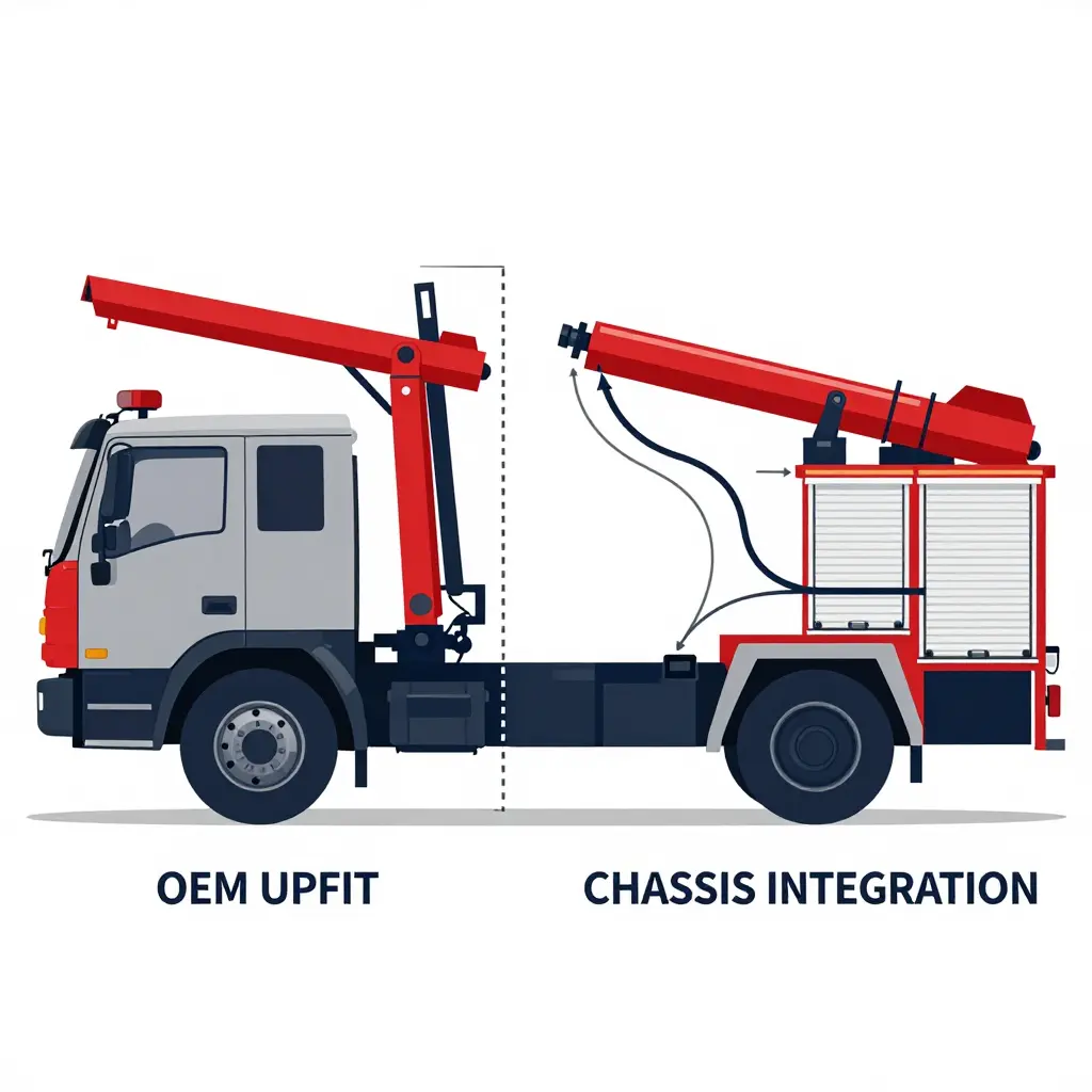
OEM Upfit: A Supplied Chassis, a Split Design Responsibility
In an OEM upfit, a specialist fire apparatus upfitter starts with a commercially supplied chassis: cab, frame, driveline and emissions package already certified by the truck manufacturer. The upfitter engineers and mounts the body, pump module, tank, compartments and foam system on top of that platform.
What holds the arrangement together is a set of defined interface boundaries: designated frame drilling zones, PTO and pump-drive take-off points, coolant and air routing, electrical tap-in locations, and a documented list of mounting hardware and torque values. Because the boundary is explicit, the split of design responsibility is contractual rather than assumed. The chassis OEM warrants its frame and driveline; the upfitter warrants the body, module and interface hardware.
Interface decisions then carry more weight than they look. If the pump module lands with an unfavourable centre of gravity, or the electrical take-off exceeds a chassis circuit’s headroom, the failure can fall into the gap between two warranty owners. Writing the interface down at specification stage is what closes that gap. Platform choice usually drives the conversation, because available frame length, rail section and front axle rating set the payload budget before any body design starts; see the range of heavy-duty fire truck chassis options for the typical envelope.
Chassis Integration: One System, One Engineering Scope
Chassis integration treats chassis and body as a single engineered system. Frame rail section, reinforcement, outrigger placement and body sub-structure are designed together around the actual pump, tank and equipment loads, so load distribution follows a planned path from the module mounts down to the axles.
Wiring follows the same logic. One harness architecture, one telematics gateway and a defined CAN/J1939 message set mean body functions, pump controls and fleet telemetry share a single network instead of two bridged ones. Weight and centre-of-gravity management then becomes a design variable rather than an after-the-fact check, because tank baffling, compartment layout and component placement are iterated against axle load targets while the package is still on the drawing board. Commercial chassis still work inside this model, but the commercial fire truck chassis platforms have to be judged on rail capacity and CAN openness, not cab comfort alone.
Because one engineering team owns chassis, body, electrical and weight outcomes, single-point accountability replaces interface negotiation.
Side-by-Side: Six Decision Dimensions
| Dimension | OEM Upfit | Chassis Integration |
|---|---|---|
| Engineering control | Authority stops at the interface line; frame and driveline changes need OEM sign-off | One authority across chassis and body; changes move faster but carry full in-house burden |
| Weight optimization | Works inside a payload budget set by the chassis OEM; body additions shift CoG rearward | Load paths and tank placement designed to axle targets from the first layout |
| Homologation and certification | Base chassis certified; upfitter still owns body-related compliance and any weight re-rating | Whole vehicle certified as one submission, with the full burden on one party |
| Serviceability | Familiar commercial chassis parts network; interface hardware and module serviced by the upfitter | Coherent documentation, but purpose-built parts can extend lead times |
| Lead time | Chassis availability plus upfit build, often in parallel | Serialized design and build; longer first unit, shorter repeats |
| Total cost of ownership | Lower acquisition cost; interface repairs and dual warranty paths add lifetime risk | Higher capital outlay; fewer interface failures and simpler warranty handover |
Engineering Control and Change Cycles
Engineering authority in an OEM upfit stops at the interface line. Any change to frame drilling, driveline rating or chassis electrical capacity needs the chassis OEM’s approval, so the change cycle lengthens, but the OEM warranty survives the change. Inside chassis integration the same change is one internal decision: a shorter loop for a heavier in-house engineering load.
Weight Optimization and Centre of Gravity
Upfit weight calculations start from a payload figure the chassis OEM has already published. Add a full water tank, pump and foam system behind the rear axle and the centre of gravity moves rearward, taking front axle share and braking margin with it. Discover that at weigh-in and the remedies are ballast, derating or a tank redesign. In an integrated design the shift gets caught at the layout stage, so the vehicle reaches its axle targets without corrective steel.
Homologation and Certification Effort
The commercially supplied chassis already holds its type approval and emissions certification, which removes a large block of work from the upfitter. What remains – brake performance at the increased gross weight, lighting, rear underrun protection, load distribution documentation – is still the upfitter’s to prove. Chassis integration folds all of it into one submission. The dossier gets simpler, and every verification step lands on one team.
Serviceability in the Field
An upfitted apparatus gives a department access to a national commercial parts network for cab, engine and driveline items, while body and module work routes back to the upfitter. An integrated vehicle presents one service manual and one warranty contact, but proprietary components can stretch parts lead times and keep the truck out of service longer.
Lead Time
Chassis procurement and body design can run in parallel, so an upfit can compress the first build when a suitable chassis is in stock or on allocation. Integration serializes the two, which lengthens the first unit but tends to shorten repeat builds once tooling and documentation settle.
Total Cost of Ownership
Upfront, OEM upfit is usually the lower-capital route. Over the service life the account balances against interface-related repairs, dual warranty claims and the labour of coordinating two suppliers. Chassis integration costs more to acquire and less to keep: fewer interface failures, one warranty relationship, and a documented pump module fitment that survives crew turnover and a mid-life refurbishment.
Matching the Route to the Requirement
- Choose OEM upfit when chassis availability, familiar service networks and faster first delivery outweigh interface administration.
- Choose chassis integration when axle loading, pump module fit and telematics depth are fixed requirements rather than negotiable ones.
- Whichever route you take, freeze the interface or system document before build and hand it over with the warranty. That single artefact decides who answers the phone in year four.
Responsibility on a fire apparatus rarely splits neatly down the middle, and procurement teams feel the friction when it does. The table below sets the two build models side by side.
Responsibility boundaries across both build models, for confirming which party owns each decision before contract award.
| Criterion | OEM Upfit Responsibility | Chassis Integration Responsibility | Decision Guidance for Procurement |
|---|---|---|---|
| Design authority | Owns body layout, module drawings and equipment packaging | Owns frame, cab and driveline architecture | Name one design owner before contract award |
| Chassis and frame modification | Requests mounting points, cutouts and reinforcement locations | Approves frame drilling, welding and structural reinforcement | Require written frame approval before finalizing overall length |
| Weight and center-of-gravity control | Controls body, water tank and foam tank weights | Certifies axle loads and final center-of-gravity position | Demand one combined weight and CG report at design freeze |
| Pump and PTO drive interface | Specifies pump module, plumbing runs and PTO interface | Delivers PTO-ready transmission and rated engine output | Lock the pump-to-PTO interface in one signed document |
| Electrical and CAN architecture | Owns body controls, lighting multiplex and pump logic | Provides chassis CAN gateway and vehicle data feeds | Agree one CAN protocol plus a fault-responsibility matrix |
| Certification and standards documentation | Holds body-related NFPA 1901 test reports | Holds chassis emissions, braking and crash certification | Combine every certificate in a single handover dossier |
| Warranty ownership | Warrants body, pump and all installed components | Warrants chassis, engine and transmission coverage | Appoint one warranty administrator for the fire department |
| Spare parts and service network | Supplies pump, valve and body spares | Supplies engine and driveline parts | Confirm both networks in writing before delivery acceptance |
| Typical lead time | Upfit builds run roughly sixteen to thirty weeks | Chassis supply and delivery runs six to twelve months | Set milestones against the longer of the two schedules |
| Best-fit application | Standard pumpers and quick-turn fleet replacement builds | Aerial, ARFF and specialized heavy apparatus programs | Match integration model to call volume and mission profile |
Treat the table as a negotiation checklist, not a fixed rulebook. On some programs the chassis supplier also carries body integration, which collapses two columns into one accountable party. Wherever the split sits, confirm spares coverage early against a documented fire truck parts catalog, so the handover dossier closes with parts availability as well as warranty signatures.
Interface engineering decides whether a quotation becomes a durable fire truck apparatus or a warranty claim. Every number agreed at bid stage, whether rail section, mount spacing, tank position or valve stack location, becomes a commitment the vehicle has to live with through twenty years of duty cycles. These are the interfaces that fail most consistently when an upfit gets treated as a bolt-on rather than a system.
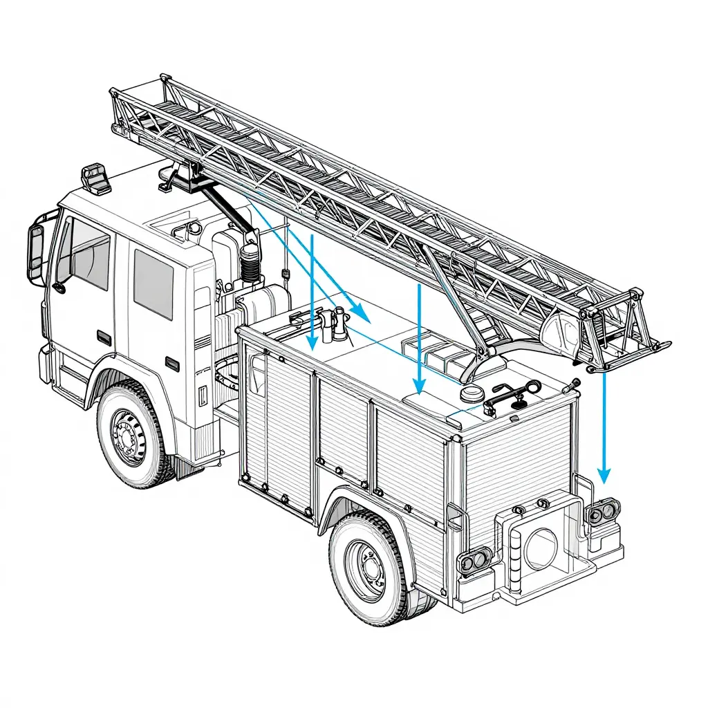
Structural and Hydraulic Interfaces That Decide Service Life
Frame rail reinforcement and subframe mounting. OEM rails are rated for the loads their designers imagined, and bolting on a tank, pump and foam system rewrites the bending moment diagram. Reinforcement should follow the rail, with innerliners or flitch plates running continuous past the highest stress zone and matched to the rail steel grade and fastener class. Clamp spacing, hanger type and bolt torque matter more than plate thickness. Heat-treated rails must not be welded without OEM approval, and any hole drilled in a flange needs a documented, stress-checked location.
Torsional and bending load paths. A body is either rigidly coupled or flexibly mounted at three or four points, and the drawing has to say which. Over-constrain the frame and normal rail twist turns into cracked welds at the rear body mount. Under-constrain it and the module walks, fretting plumbing fittings loose within a season. Crossmember placement, mount compliance and shear versus tension loading in fasteners belong on the interface drawing, not in the fitter’s judgement. Hardware carries equal weight: spring hangers, body-mount bushings and matched-grade fasteners sourced as part of a planned chassis integration hardware package remove one of the most common field failure modes.
Rear axle and suspension load budget. Tank position drives everything downstream. Water ahead of the rear axle improves traction but loads the front GAWR; water behind it unloads the front axle and dulls steering response. The budget belongs in a table the whole project team signs, not in a spreadsheet buried in the quote file.
| Budget item | Quotation-stage assumption | Field consequence if wrong |
|---|---|---|
| Front GAWR | Tank set forward, nominal margin claimed | Axle overload, tyre and brake duty rise |
| Rear GAWR and spring rate | Payload split 40/60 front to rear | Sag, reduced roll stiffness, uneven braking |
| Frame rail section | Standard rail with bolted flitch | Rail cracking at mount transitions |
| Mount configuration | Four-point flexible, specified compliance | Over-constrained twist, weld fatigue |
| Baffle load case | Longitudinal surge at partial fill | Tank movement, cracked baffle welds |
| Module space claim | Pump and foam inside body width | Controls relocated, service access lost |
Tank mounting and baffling loads. Baffles exist to convert slosh into structure, so the tank mounts and subframe have to resist the resulting surge plus the vertical and lateral cases. Isolation pads should stop the shell abrading the rail while still transmitting load through a defined path. A tank that is quiet at full fill often knocks hardest at half fill, which is the case the quote usually omits.
Hard plumbing and valve access. Pipe routing should respect minimum bend radii, isolate vibration with supported standoffs and keep every valve reachable from grade or from a single access hatch. Fittings tucked behind a foam tank do not get maintained, and a drain point that requires removing a panel does not get used. Pressure loss across elbows and valves is a fit issue that resurfaces later as a pump performance complaint.
Space claim for pump, foam system and controls. The pump module, foam proportioner, tank and control panel compete for the same envelope, and space is usually conceded in that order of priority. Reserve clearance for panel removal, hose connections and operator reach before the body layout is frozen.
Each of these assumptions propagates straight into the field. An optimistic rail rating shows up as a cracked mount at 40,000 km. A generous payload figure shows up as an overweight axle at the weighbridge and a compliance letter to the fleet manager. A compressed module shows up as warranty labour for a valve nobody can reach. Fixing them at quotation costs drawings; fixing them in service costs credibility.
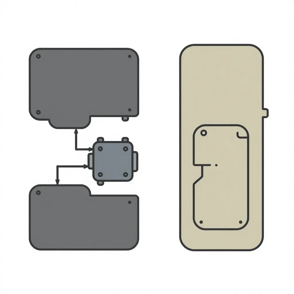
Schematic: the interface-boundary principle behind OEM upfit versus chassis integration.
Pump Module Fit: Drive Choice, Driveline Geometry, and Everything It Locks In
A fire pump module does not drop into leftover frame space. It loads the chassis structurally, torsionally, hydraulically and thermally at once, and pump module fit decides wheelbase, hosebed depth, compartment depth, water tank shape and even the position of the rear axle before anyone draws a compartment layout.
Get the drive architecture wrong and the error propagates through the entire body. Fix it late and you re-engineer plumbing, mounts and sheet metal together.
Start With How the Pump Takes Power
Every fire pump module starts with one question: does the pump interrupt the chassis driveline, or hang off it? The answer sets the chassis spec, the frame length and the service philosophy.
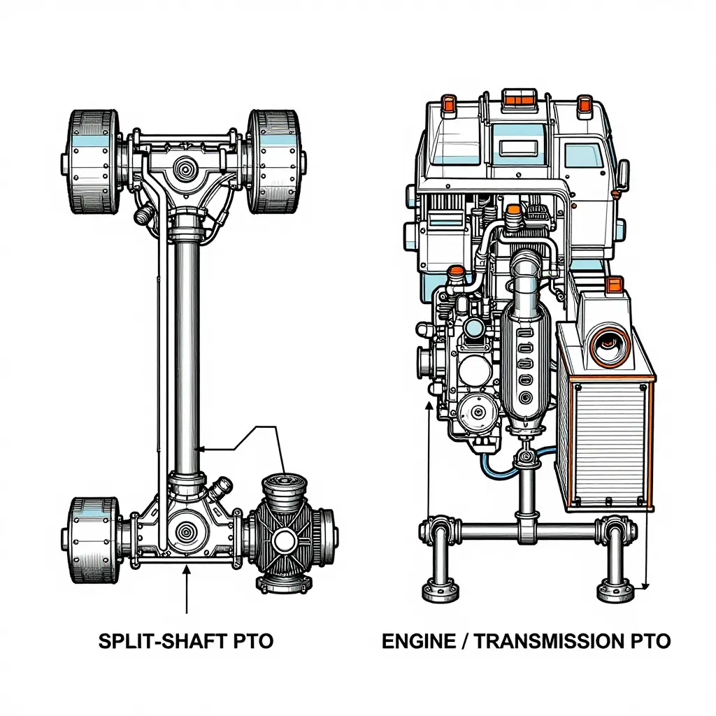
A split-shaft PTO replaces a section of the main driveshaft with a transfer case that carries a second output to the pump. The pump becomes a driven element inside the driveline, which is why mid-ship pumps can deliver pump-and-roll, and why the chassis must be rated for pump torque reacting through the frame.
An engine- or transmission-mounted PTO drives a short auxiliary shaft to the pump instead. It leaves the chassis driveline untouched, but it lives or dies on PTO torque rating, transmission oil cooler capacity, and the geometry of a shaft that has to reach forward past the engine or rearward under the cab.
| Criterion | Split-shaft PTO (mid-ship) | Engine / transmission PTO |
|---|---|---|
| Power path | Main driveline interrupted by transfer case | Independent auxiliary shaft from engine or transmission |
| Chassis demand | Long clear frame bay between axles; reinforced rails | Free space at pump location; PTO port availability |
| Driveline impact | Two additional universal joints, added mass and inertia | None to the main driveline |
| Pump-and-roll | Yes, with transmission in pump gear | Generally limited or unavailable |
| Typical capacity ceiling | 1,250 to 2,250 gpm depending on frame and shaft | 750 to 1,500 gpm, torque-limited |
| Cooling load | High; pump gearbox plus engine at full load | Moderate; heat rejection through PTO lube circuit |
| Service access | Pump body reachable from beneath and through panel | Often tighter, shaft coupling hidden behind cab |
| Best fit | High-flow structural and attack pumpers | Rescue, quick-attack and combination bodies |
Driveline Angle and Clearance Limits
Universal joints do not tolerate large angles under continuous load. On a pump driveshaft run, aim for joint angles that cancel to within 1 degree of each other, continuous operating angles under 3 degrees, and intermittent angles capped near 15 degrees at low shaft speed.
Pump input flanges should sit parallel within about 0.5 degree, runout should stay inside 0.005 to 0.010 inch total indicator reading, and the slip spline should keep at least an inch of engagement through full suspension articulation.
Clearance has numbers too. Maintain roughly one inch minimum between the rotating shaft and frame rails, air tanks, fuel lines, wiring harnesses and tank skins, verified at full bump and full droop, and fit a shaft safety loop regardless.
Clearance disappears fastest on the suction side. A 6-inch intake elbow needs vertical drop below the pump inlet, and that drop competes with the frame rail, the front axle beam and the bumper. Lay out the suction elbow first and the pump second, never the reverse.
Pump Mounting and Vibration Isolation
Rigidly tying the pump to both the frame and the body creates a resonance problem you cannot tune out later. Use a dedicated subframe carrying the pump, gearbox and manifold, then isolate that subframe at three or four elastomer points rated for the pump’s static and dynamic loads.
Isolators should deflect roughly 0.06 to 0.125 inch at rated load. Torque all fasteners before final pump-to-shaft alignment, and shim rather than preload. Never let the plumbing become the structural tie between pump and body: flexible couplings, expansion loops and slip joints belong at every crossing.
Pump discharge piping needs its own support as well. A manifold hanging off the pump casing turns pressure pulsation into fatigue cracks at the weld neck.
Suction and Discharge Plumbing: Sizing, Bends, and Fitting Losses
Size pipe by velocity, not by habit. Keep intake velocity below roughly 15 feet per second at rated flow and discharge mains below 25 feet per second to limit erosion and noise.
| Nominal pipe inside diameter | Flow area (sq ft) | 1,000 gpm | 1,500 gpm | 2,000 gpm |
|---|---|---|---|---|
| 4 inch | 0.087 | 26 ft/s | 38 ft/s | 51 ft/s |
| 5 inch | 0.136 | 16 ft/s | 25 ft/s | 33 ft/s |
| 6 inch | 0.196 | 11 ft/s | 17 ft/s | 23 ft/s |
| 8 inch | 0.349 | 6 ft/s | 10 ft/s | 13 ft/s |
That is why 2,000 gpm rarely works through a single 6-inch suction line. Either the intake grows to 8 inch, or the design moves to dual 6-inch intakes into a common manifold.
Bends add the second cost. A standard-radius 90-degree elbow is worth about 30 pipe diameters of equivalent straight length; a long-radius elbow about 14. On a crowded pump panel the total builds quickly.
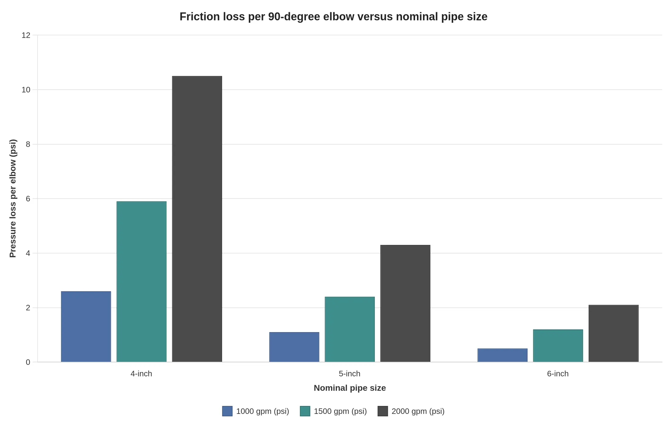
At 2,000 gpm, one 4-inch elbow costs close to 10 psi, and three of them plus a tee cost more pressure than the hose line feeding them. Every elbow, strainer, check valve and valve body belongs in the hydraulic calculation as equivalent length, not waved through as a rounding error.
Hydraulic power demand follows the same arithmetic: gpm multiplied by psi, divided by 1,714, then divided by pump and drive efficiency. A 1,500 gpm pump at 150 psi needs roughly 190 brake horsepower at the pump shaft at 70 percent efficiency, before accessory loads.
Valve and Control Placement
Group intake and discharge valves inside a single operator reach envelope. Handwheels and linkages must not cross the sight line to pressure and vacuum gauges, and every valve needs a visible position indicator plus a labelled function plate.
Master intake and discharge drains belong low and outboard. The relief valve or pressure governor must sense downstream of the pump discharge flange, and the control head should be readable from one standing position at the panel, hood up, in gloves.
Cooling and Airflow
Pump and engine heat rejection share one radiator. Keep the pump gearbox oil cooler out of the radiator’s inlet air path, preserve at least two inches between fan shroud and any module face, and avoid the dead-air pockets that foam tanks or hosebed floors create.
Recirculation lines matter too. A pump run at low flow must be able to return water to the tank to shed heat, and that return line needs its own sizing and a visible temperature indication.
Foam Proportioning Module Space
Around-the-pump proportioning needs almost no space but punishes intake pressure variation. Balanced-pressure and direct-injection systems need room for a concentrate pump, ratio controller, flush water and placards, typically 12 to 24 inches of working clearance for service.
Give the foam module its own dry, drainable bay and route concentrate lines without low spots or rising runs that trap air. On configurations built around foam attack roles, the proportioner envelope should be reserved at concept stage; see these foam fire truck configurations for how proportioning space is packaged against pump and tank.
Access for Service and Annual Performance Testing
Annual performance testing to NFPA 1911 requires the pump to be run at 100 percent rated capacity at 150 psi, 70 percent at 200 psi and 50 percent at 250 psi. That test needs draft hose connections, calibrated gauge taps at both intake and discharge, a flowmeter or pitot layout, and enough room to operate drains while the panel is live.
Design for the test, not just for the install. Provide gauge tap ports on both sides of the pump, accessible gearbox fill and level plugs, seal and packing access, and valve service room so a stem can be repacked without removing the manifold.
How Pump Module Selection Constrains Body Layout
Once the module envelope, driveshaft run and suction drop are fixed, the body is largely determined. Frame length drives wheelbase and turning radius. Pump position drives crosslay height and hosebed depth. The manifold drives compartment depth. The tank has to wrap around whatever volume the module leaves.
High-flow pump-driven configurations tighten all of these at once, which is why large pump platforms often pair with elevated waterways and high-volume appliances, as on water tower fire truck platforms where pump capacity and body geometry are solved as one system.
Why Late Capacity Changes Are So Expensive
A capacity bump late in the program is never a pump swap. It cascades:
- Larger suction and manifold, which changes valve bodies, flange bolt patterns and panel cutouts.
- Higher engine torque and heat rejection, which changes radiator, fan drive and cooler routing.
- Longer or deeper module envelope, which moves the wheelbase, hosebed and tank.
- New isolator rates and shaft geometry, which invalidates structural and alignment sign-off.
- Revised hose layouts, which trigger a new performance test and new warranty documentation.
Freeze pump capacity before body release. Treat pump module fit as a first-order design decision and the plumbing, mounting and cooling work stays predictable instead of turning into re-engineering.
Pump Module Fitment Parameters: A Representative Side-by-Side
Fitment risk in a fire apparatus build rarely shows up in one number. It accumulates across schedule, rework exposure, change tolerance, and how easily a crew can reach the pump after the body goes on. The chart plots all four parameters on a common 0-10 comparative index so the two build approaches can be read at a glance. Engineering lead time and rework probability are inverted, meaning a taller bar always represents the more favorable outcome.
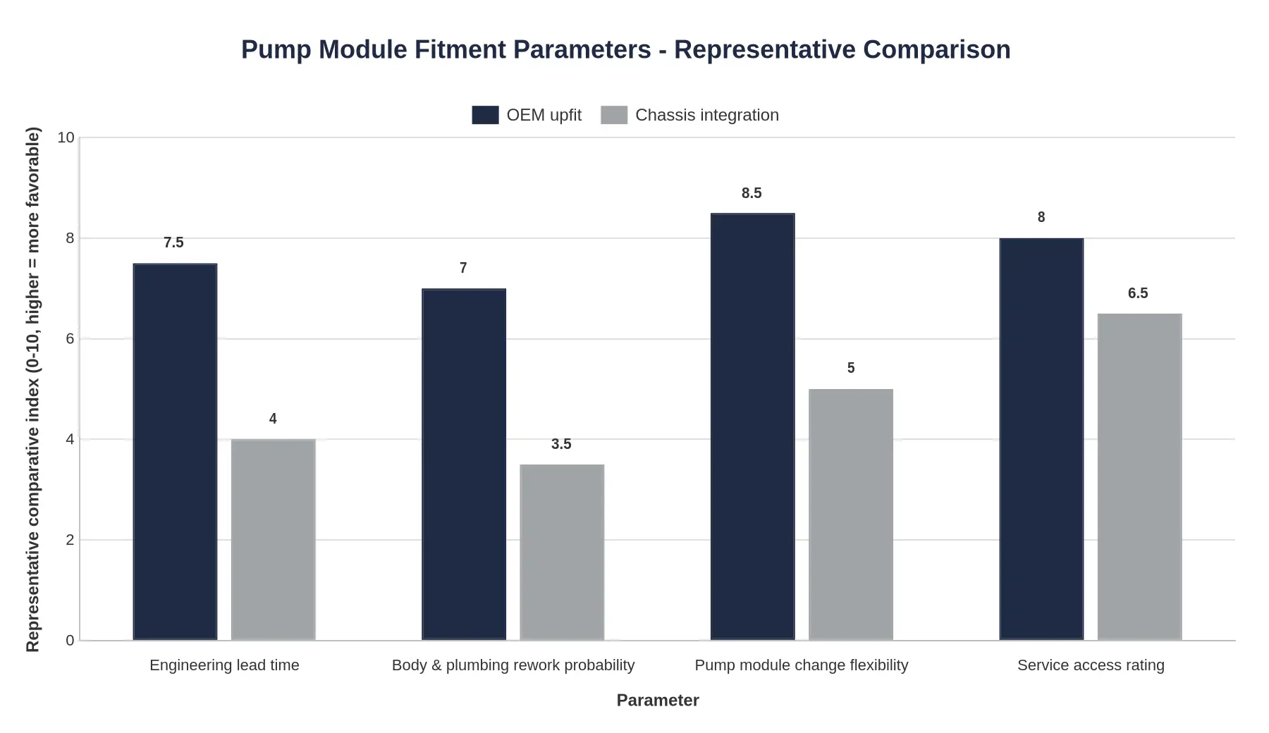
Note on the data: every value here is a representative, illustrative figure chosen to show directional differences between approaches. These are planning-level comparison values, not measured field data, and actual results vary by chassis, pump module, body configuration and upfitter.
Reading the Native Units
The index normalizes four different units onto one scale. For procurement and engineering discussions, the underlying representative values are more useful:
| Parameter | OEM upfit (representative) | Chassis integration (representative) | Favorable direction |
|---|---|---|---|
| Engineering lead time | 6 – 8 weeks | 12 – 16 weeks | Shorter |
| Body and plumbing rework probability | About 5% of units | About 18% of units | Lower |
| Pump module change flexibility | 9 / 10 | 5 / 10 | Higher |
| Service access rating | 8 / 10 | 6.5 / 10 | Higher |
What the Gap Means in Practice
- Engineering lead time diverges first. An OEM upfit starts from a validated pump-to-frame interface with known deck heights and driveline clearances, while chassis integration often requires fresh CAD reconciliation and a steering or suspension interference review before plumbing routes can be released.
- Rework probability follows lead time closely. When intake and discharge penetrations are set against a body that was not designed around the pump module, field modifications to crossmembers, brackets and hose runs become a normal cost line rather than an exception.
- Change flexibility matters most mid-program. A late pump swap, added foam proportioner or revised valve layout is a documentation exercise on an OEM upfit and a structural exercise on a fully integrated chassis.
- Service access is a life-cycle parameter disguised as an ergonomic one. Bracket-free clearance around the pump, strainer and valve manifold determines whether a two-hour service call becomes a two-day body lift, and it shapes the warranty handover conversation with the fire department directly.
Ask each bidder to submit the pump module interface drawing, the service access envelope, and a written statement of which party owns rework on body and plumbing penetrations. Those three documents, more than any single benchmark number, predict how the handover will go. Departments standardizing across a fleet can also review compatible fire truck pump and apparatus parts to confirm spares coverage before the warranty period closes.
This checklist closes fitment gaps at specification stage, before the pump module design is released to procurement and chassis build.
- Confirm driveline angles at loaded ride height and verify U-joint slip and clearance through the full suspension travel envelope.
- Verify pump mounting hard points, elastomer isolators and frame reinforcement details against the body-builder load limits published by the chassis OEM.
- Route suction, discharge and drain plumbing at defined bend radii, then confirm every valve handle and actuator stays reachable from grade.
- Position control panel and gauge clusters inside the operator’s primary reach envelope, checking glare, legibility and unobstructed sightlines to the pump.
- Allocate a documented space claim for the proportioner, concentrate tank and foam lines within the selected foam fire truck systems envelope, including service removal room.
- Verify the cooling airflow path to radiator and charge-air cooler is not obstructed by module enclosure panels, plumbing runs or auxiliary equipment.
- Confirm access for pump performance testing, including gauge taps, flowmeter ports, hose connections and safe discharge routing without body panel removal.
- Document the agreed fit envelope, dimensions, clearances and tolerance stack-ups in a signed interface document before specification release.
Treat the completed checklist as the release gate: no pump module specification should advance to fabrication until every line carries a named sign-off.
Warranty Handover: Defining Accountability Before the Keys Change Hands
Warranty handover is the point at which commercial risk transfers from the build team to the fleet. On a single-source apparatus, one party warrants the whole vehicle: chassis, body, pump module, electronics and finish. The fire department files one claim, through one channel, against one set of terms. Negotiating that structure costs more up front, but it collapses ambiguity to a single accountable entity.
A split warranty distributes the same coverage across parties. The chassis OEM warrants the powertrain and cab electrical architecture, the upfitter warrants the body, the pump module builder warrants the fire pump and plumbing, and the electronics integrator warrants the multiplex system. Each warranty carries its own duration, exclusions, labor rate and claim portal. For fire truck apparatus manufacturers building customized configurations, split coverage is common because the underlying components rarely share a single warranty term.
What Must Be Documented at Handover
The documentation package is the evidence base for every future claim. Incomplete handover records, not failed components, are the most frequent reason legitimate claims get denied.
| Record Set | Contents | Warranty Function |
|---|---|---|
| Interface design records | Interface control drawings, load and torque calculations, wiring and CAN schedules, PTO engagement logic, cooling and airflow assumptions | Establishes design responsibility for every shared boundary |
| Component serials and build records | Chassis VIN, pump serial, engine and transmission serials, module serials, ECU and multiplex IDs, build and in-service dates | Fixes warranty start dates and identifies the exact warranted unit |
| Commissioning and pump performance test results | Rated capacity and pressure tests, 100 percent and 70 percent flow runs, vacuum and priming checks, relief valve settings, ambient conditions | Proves the apparatus was delivered to specification and dates the baseline |
| Approved modification log | Authorized deviations, field changes, software revisions, sign-off by responsible party | Distinguishes approved work from unauthorized alteration |
| Boundary conditions statement | Defined limits for third-party modification: wiring taps, pump re-plumbing, structural additions, engine or PTO recalibration, electrical load additions | Defines precisely which modifications void coverage and for which party |
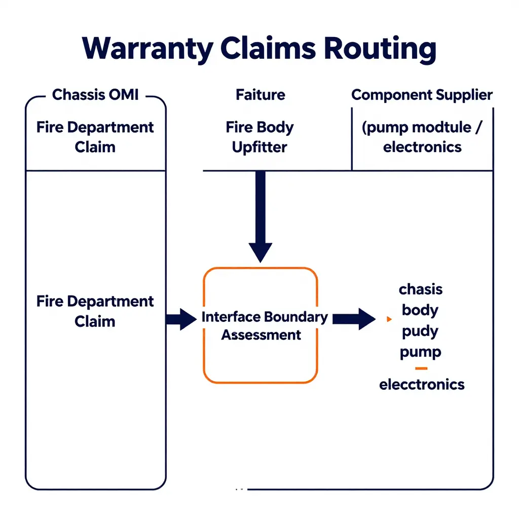
Claims routing follows the same map. An intake review identifies the failure origin, the responsible party accepts or rejects ownership in writing, and the claim moves to that party’s process. Diagnostics labor, towing, downtime and consequential damage are usually the contested line items, so they should be assigned in the handover agreement rather than negotiated after a failure.
Disputes start where interface ownership is ambiguous. A pump that underperforms may be a pump problem, a PTO ratio problem, a cooling deficiency in the body package, or a chassis derate triggered by an electronics fault. When the interface design record is silent on who owns the boundary, each party can present a defensible case for exclusion, and the fire department absorbs the loss. Naming an owner at every interface is the only reliable prevention.
Typical Warranty Responsibility Split in a Fire Apparatus Project
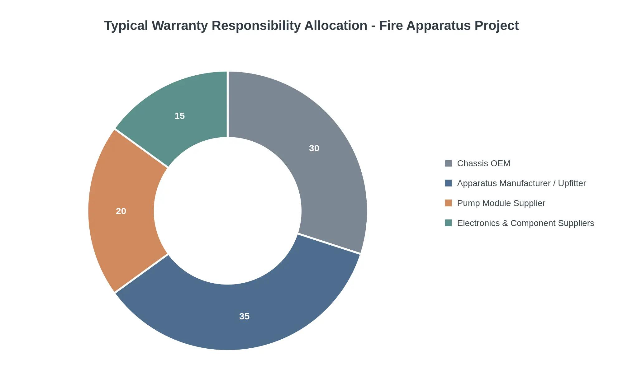
Figure: Indicative warranty responsibility allocation by party. The apparatus manufacturer or upfitter typically carries the largest share, since it owns final assembly, body-to-chassis interfaces and the overall performance guarantee. The chassis OEM retains its own powertrain, frame and cab coverage, while the pump module supplier and electronics vendors warrant their own assemblies.
Caption note: these proportions are indicative and shift between delivery models. In an OEM upfit the chassis builder may absorb more interface responsibility, whereas in full chassis integration the upfitter carries a larger share of the warranty handover.
The numbered sequence below reflects the order in which a complete warranty handover package should be assembled and signed off. Each signatory’s approval is only valid once the evidence cited in the preceding item is verified and attached to the file.
- Interface design and boundary drawings that show how responsibility is split between chassis OEM and upfitter, including mounting points, PTO interfaces and connection tolerances.
- Component serial and build records that trace every pump, valve and module to its manufacturing lot, assembly date, torque values and component-level documentation.
- Commissioning and pump performance test reports covering rated flow, pressure, priming and overload results against the approved acceptance criteria for the module.
- The approved modification and change log, carrying every deviation from released specification with its engineering approval, revision number, date and affected assembly.
- Warranty coverage matrix by subsystem: coverage duration, start date, exclusions and supplier back-to-back terms for each major assembly.
- Claim routing and escalation contacts: who receives each claim, tier-by-tier response timelines, decision authority and escalation paths to OEM suppliers.
- Operator and maintenance documentation showing that operating limits, service intervals, lubrication schedules and parts lists support warranty-compliant use and inspection.
For upfitters specifying equipment on fire fighting truck platforms, keeping this sequence visible during final inspection shortens the sign-off cycle and prevents warranty disputes months later.
The Warranty Handover Package, Stage by Stage
A handover package is a sequence, not a stack of paper. The diagram below shows the four stages it follows.
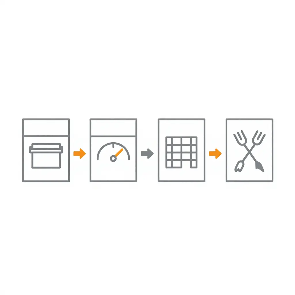
Interface documents define what was integrated, commissioning records prove it performs, the coverage matrix assigns responsibility line by line, and claim routing tells the fleet who to call. Keep the same identifiers – VIN, pump module serial, build sheet – running through all four stages, so a claim filed in year six traces back to the record that supports it. Departments that maintain this chain, and stock traceable fire truck parts behind it, spend far less time arguing about coverage and more time back in service.
Frequently Asked Questions: OEM Upfit, Pump Module Fit and Warranty Handover
These five questions come up most often in specification meetings, bid clarifications and post-delivery reviews. Answers are kept short and self-contained; where a component decision affects the whole apparatus, we point to the relevant fire truck parts and pump module hardware for reference data.
Can OEM upfit match chassis integration for weight and center-of-gravity control?
Yes, when the upfitter designs from OEM CAD models, uses factory body-mount points and stays inside the published payload envelope. OEM upfit then matches chassis integration, provided axle loads and vertical center of gravity are measured at each build stage rather than estimated.
What documentation resolves pump module fit disputes?
A signed interface control document: mounting envelope, PTO and driveshaft geometry, port locations, plumbing clearances and a tolerance stack-up. Pair it with dimensional inspection reports taken at receiving, so any pump module fit dispute is settled against measured data rather than opinion or memory.
Who owns the warranty when the chassis and pump module come from different suppliers?
Each supplier warrants its own component, while the upfitter carries the integrated system. The contract must define responsibility boundaries, labor reimbursement rates and one single claim contact, so the fire department never has to arbitrate between chassis and pump suppliers during an outage.
How do late pump capacity changes affect body and plumbing engineering?
Badly, and expensively. A larger pump demands bigger suction and discharge lines, a revised valve layout, more cooling capacity and often a longer body. Lock pump capacity before design freeze, or budget for rework, fresh stress analysis and recertified weight distribution.
What should procurement require at warranty handover?
At warranty handover, demand the complete package: component warranty statements, serial numbers, commissioning and pump performance test records, as-built drawings, maintenance schedules, and a named service contact with written response times. Incomplete packages shift risk to the department on day one.
Closing the Specification: A Decision Framework
Choosing between OEM upfit and chassis integration is an engineering determination, made early, documented, and defended through the build. Treat it as one and most downstream disputes never materialize.
When OEM Upfit Is the Right Starting Point
Choose OEM upfit when the mission profile sits close to a proven production platform. If the body envelope, axle loading and PTO or split-shaft drive geometry are already validated as a system, the upfitter inherits a known baseline and the risk stays contained. Repeatable fleet orders, compressed delivery windows and familiar pump-and-plumbing architecture all point in this direction.
When Chassis Integration Is the Right Starting Point
Choose chassis integration when the mission demands divergence. A non-standard wheelbase, unusual weight distribution, repower requirements or a performance envelope no production platform satisfies all mean the chassis itself becomes a design variable. That is routine for application-specific configurations such as industrial fire truck builds serving petrochemical sites, and equally true for airport fire trucks, where acceleration, foam delivery and pump-and-roll behavior are specified as a package rather than assembled from standard parts.
| Decision Signal | OEM Upfit | Chassis Integration |
|---|---|---|
| Mission profile | Standard structural or urban pump response | Specialized performance envelope |
| Body envelope | Fits validated production dimensions | Requires bespoke compartment geometry |
| Drive geometry | Proven PTO or split-shaft arrangement | New driveline or repower integration |
| Order volume | Repeatable fleet order | One-off or low-volume specialist build |
| Warranty exposure | Defined OEM interface | Responsibility split across several parties |
| Schedule | Compressed delivery window | Longer, front-loaded engineering phase |
Two Rules That Do Not Bend
Pump module fit must be resolved before body layout is fixed. Piping runs, valve access, intake and discharge clearances, and service space are all downstream of that decision. Locking compartment dimensions first guarantees rework, and rework on a fire apparatus is expensive in both money and delivery schedule.
Warranty handover boundaries must be written into the specification rather than settled after delivery. Naming who owns the pump, the driveline interface, the electrical architecture and the corrosion exposure in the contract documents removes the ambiguity that turns a warranty claim into a negotiation. Post-delivery discussions favor the party with the better paperwork, not the party with the better argument.
Engineering Accountability Moving Forward
Fire truck apparatus manufacturers that publish their integration boundaries, define pump module fitment criteria up front and document warranty handover in the specification keep their fleets in service instead of in dispute. The apparatus that performs over twenty years is rarely the one with the most features. It is the one where every party knew exactly where its responsibility started and where it ended.