Mini Pumper Fire Trucks for Sale: Rear Axle Margin, Baffles, Gradeability
Almost every mini pumper for sale is described the same way: a compact apparatus on a light-to-medium commercial chassis, a tank of roughly 300 to 750 US gal (1,135 to 2,840 L), a mid-range pump. That description fits most small fire truck platforms on the market, so it separates nothing. The class is defined by packaging rather than performance, and the limits that decide whether a truck is worth the money rarely show up on a showroom floor.
Three numbers set those limits. Rear axle weight margin, measured against GAWR and GVWR, decides how much equipment a department can add after delivery. Baffle spacing decides whether the water load stays where the chassis engineer assumed it would during braking and cornering. Gradeability, in grade percent, decides whether the truck reaches the fire or parks at the bottom of the hill. A committee with written answers on all three can defend the specification to a council or board, and live with the purchase for the next twenty years.
Rear Axle Margin: The First Number to Verify
Rear axle margin is rear GAWR minus the actual rear axle load, measured with the water tank full, pump and foam systems charged, crew aboard, and hose, tools and ladders stowed. GAWR is a ceiling fixed by the axle, springs, tires and wheels, and it does not grow when you add equipment. Build the calculation on the loaded weight; the shipping weight will not tell you anything useful.
Water is the bulk of the payload at 8.34 lb per US gallon, so a 300-gallon tank adds about 2,500 lb (1,134 kg) as a single concentrated mass. Foam concentrate is close to water in density but rides in far smaller volume, and hand tools and crew are light for their size. Because water dominates the total, where the tank sits can matter more than how much it holds.
A rear-mounted tank or rear-mounted pump shifts load rearward, and every inch behind the rear axle adds weight to the rear axle while taking it off the front. A tank sitting behind the rear axle costs steering and braking stability, because the front tires lose normal force and grip exactly when the truck needs them on a steep, loose driveway. Rearward mass also lengthens the lever arm that pitches the chassis forward under braking.
Keep a measurable percentage of rear GAWR in reserve, typically 10 to 15 percent, rather than loading to the limit. That reserve covers equipment growth, tire rating headroom and per-axle tire load limits, which are often stricter than the axle itself. GVWR is a separate overall cap, so a compliant rear axle does not guarantee a compliant truck.
Before signing, get these weights from the dealer:
- Rear GAWR and front GAWR from the axle and spring tags, not the brochure.
- A certified scale ticket for the loaded rear axle with tank full, foam cell full and crew aboard.
- Curb weight plus tank, pump and foam capacities converted to fluid weight.
- Per-axle tire load ratings, including load range and single versus dual configuration.
When comparing small fire truck chassis options, ask for the rear axle margin in writing. On a light fire truck chassis the gap between rated and loaded weight is small, so specify axles, suspensions and springs rated for the fully loaded condition, then check the numbers on a scale before delivery. A compact fire apparatus that passes this check will steer, stop and carry equipment growth without surprises.
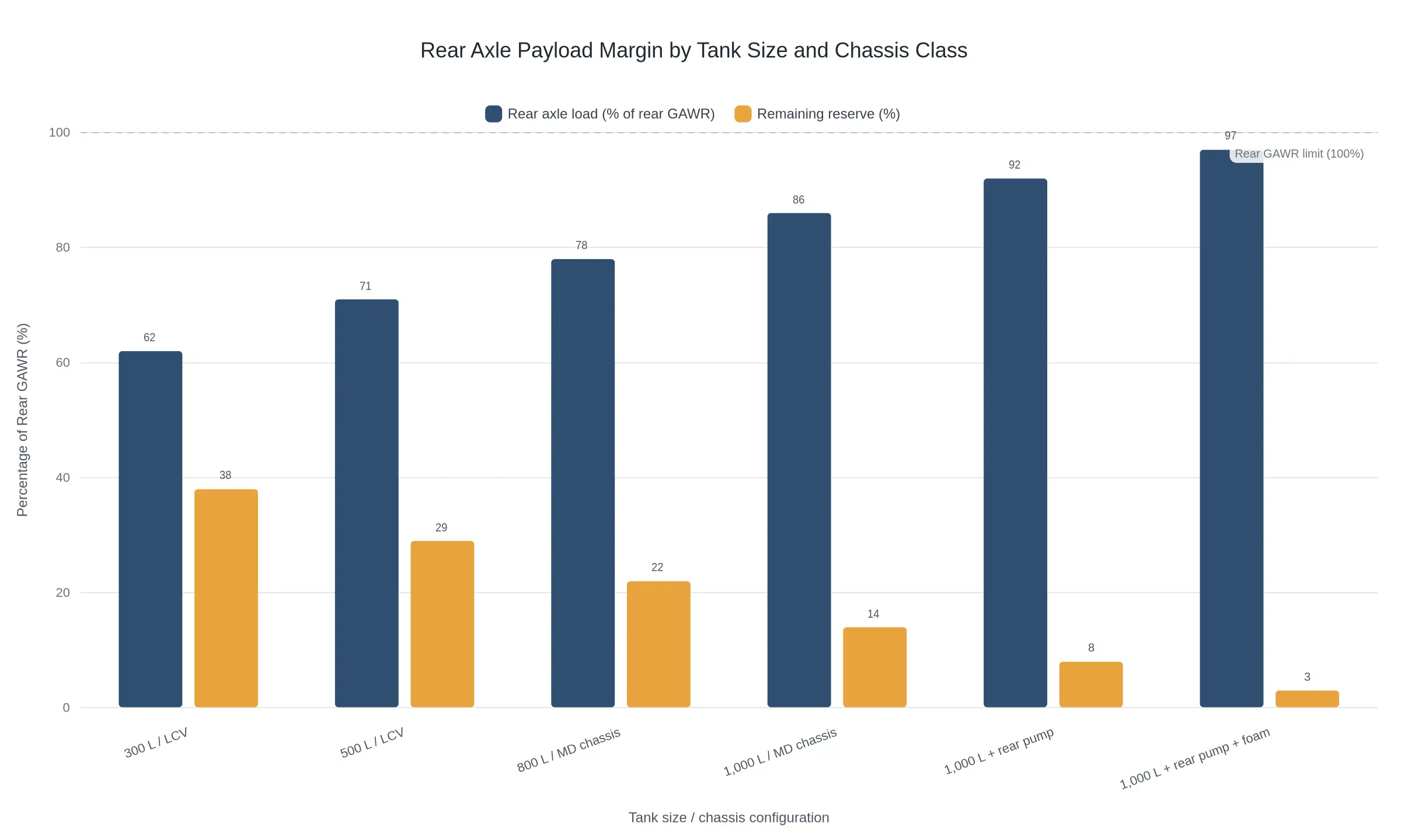
Rear axle margin shrinks from a comfortable 38% reserve at 300 L to just 3% once a 1,000 L tank carries a rear-mounted pump and foam system.
Annotation – underlying values (rear axle load % of rear GAWR / remaining reserve %): 300 L on LCV = 62 / 38 · 500 L on LCV = 71 / 29 · 800 L on medium-duty chassis = 78 / 22 · 1,000 L on medium-duty chassis = 86 / 14 · 1,000 L + rear-mounted pump = 92 / 8 · 1,000 L + rear-mounted pump + foam system = 97 / 3. Values are representative engineering estimates; confirm against the actual chassis rear GAWR, wheelbase and completed-vehicle weigh ticket.
Tank Baffles: Controlling Water Movement on Compact Apparatus
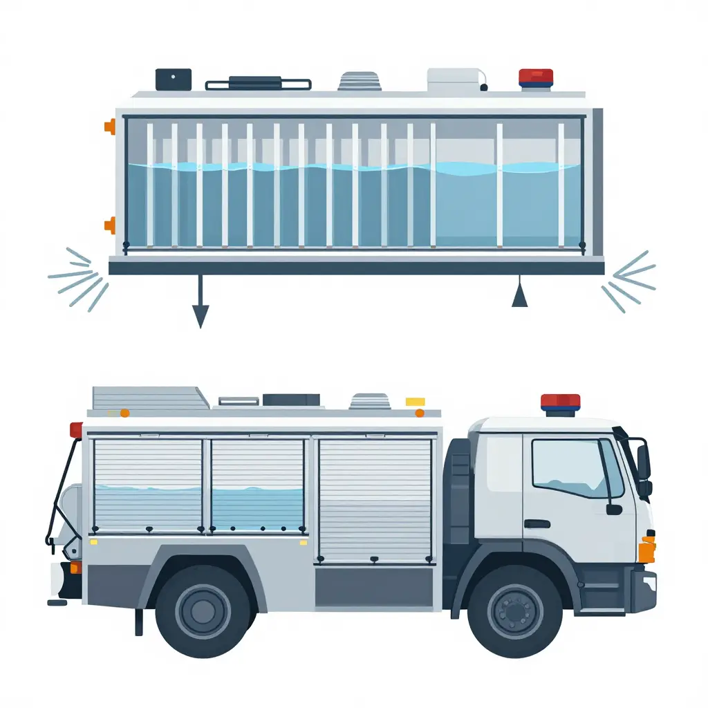
A tank full of water is a mass; a tank half full is a moving mass. On a compact chassis that distinction bites harder than on a full-size tanker, because the wheelbase and track are shorter and there is less suspension travel to absorb a shifting load. Baffles break one large moving mass into several small ones.
How Slosh Loads Develop
Without internal division, water slosh behaves as a single free surface. Under braking the liquid runs forward and piles against the front head sheet, adding a longitudinal overturning moment to the front axle at the moment weight transfer is already unloading the rear. In a corner the surge moves sideways: water rides up the outboard wall, raising the center of gravity on the loaded side and producing a lateral roll moment the springs and anti-roll bar have to resist. On a grade the free surface stays level while the tank tilts, so the liquid redistributes toward the downhill end and the center of gravity migrates away from the chassis centerline and the axle midpoints.
Why a Partly Full Tank Is the Worst Case
Free surface effect scales with the width and length of the exposed water plane, not with the volume aboard. A tank at 50 to 70 percent full presents a large continuous free surface with plenty of mass behind it, so the same lateral acceleration moves the center of gravity furthest. A nearly full tank has little free surface to slosh; a nearly empty one has little mass to move. This is where most driver complaints about “the truck walking” come from.
Subdividing the Tank
Transverse baffles run across the tank, normal to the direction of travel, and take the braking and acceleration surge. Longitudinal baffles run fore and aft and control side-to-side movement in corners. Together they form a grid of compartments. Practice on small tanks looks like this:
- Compartment spacing: transverse baffles at roughly 600 to 900 mm (24 to 36 in) centers on a mini pumper, with longitudinal baffles added when tank width exceeds about 1.2 m (4 ft).
- Open area: transfer openings sized to throttle flow rather than block it, commonly around 15 to 25 percent of the baffle face, placed low for drainage and high to let air pass.
- Plate and stiffening: baffle plate thickness matched to shell thickness, with flanged or swaged edges to resist flexing.
Welded Versus Bolted Baffles
Bolted baffles are convenient to install and to remove for inspection, but the bolted joint is a clearance fit. Each surge cycle lets the baffle rock slightly on its fasteners, fretting the mating faces and loosening preload until the connection works. Welded baffles give a continuous load path into the shell, so surge force is spread rather than concentrated at a handful of bolts. The trade-off is that a welded baffle still flexes under cyclic loading, and if the plate is thin or unsupported, the bending concentrates at the weld toe, which is where fatigue cracking in water tank baffles most often begins.
Weld quality is therefore a structural matter, not a cosmetic one. Baffles should be welded to the shell with continuous fillet welds on both sides where practicable, with no crater cracks, undercut or stop-start voids at the corners. Drainage and venting need equal attention: a weep or scupper gap at the tank floor keeps water from sitting against the weld and corroding it from the inside, while an open top edge or vent hole prevents the air locking that can over-pressure a compartment during rapid filling. Departments increasingly specify foam cell compartments built as separate, fully drained structures rather than as baffled water space, which is the safer arrangement when foam concentrate is carried on board. Buyers should ask how the builder verifies weld soundness and compartment drainage before the tank is closed up.
What to Put in the Written Specification
Require the number and spacing of transverse and longitudinal baffles, the transfer opening area and position, baffle plate thickness, continuous baffle-to-shell weld quality with the applicable inspection standard, and dedicated drain and vent provisions for every compartment.
Settle the tank specification in writing before the committee ranks prices. Tank internals are the part of a mini pumper that buyers cannot see at delivery and cannot easily change later, and answers given verbally during a demo walk-around rarely survive into the build sheet. Put every dimension, test result and attachment detail into the request for proposal, so all bidders respond to the same criteria.
Baffle and Tank Questions to Put in Writing
Send these to each supplier and require a signed written response attached to the bid. Check the answers against the pump capacity, the fill level the truck will actually carry on the grades in your response area, and the frame drilling pattern on the chassis you are considering.
- How many baffles are fitted inside the tank, and are they transverse, longitudinal, or a combination of both orientations?
- What is the clear spacing between adjacent baffles, stated as a percentage of the tank’s internal width?
- Can you supply weld inspection records and the pressure or leak test report for the completed tank?
- How is the tank body fastened to the chassis frame, and what isolation material separates dissimilar metal contact points?
- Has the tank been surge tested at rated fill and at partial fill, and what movement or stress values were recorded?
- What are the size, location, and orientation of the fill inlet, vent, overflow, and drain connections?
- What material grade and wall thickness are specified for the tank shell, the baffles, and the baffle-to-shell welds?
- What warranty period applies specifically to tank shell welds and baffle welds, separate from the general apparatus warranty?
A supplier who answers all eight items with numbers instead of adjectives is telling you something about how the rest of the build will be documented. Treat a blank or vague answer as a pre-bid discussion item, and confirm that the accepted answers are copied into the purchase contract rather than left in a quotation email.
Sustainable Speed on Grade: Loaded vs Empty Mini Pumper
Grade performance is the hardest thing to check on paper and the easiest thing to get wrong in the field. A mini pumper that feels lively on the station apron can crawl at walking pace on a gravel drive the moment the tank is full. The chart below plots sustainable climbing speed, not peak and not momentary, against grade percentage for the same chassis in two conditions: fully loaded with water and equipment, and at empty weight.
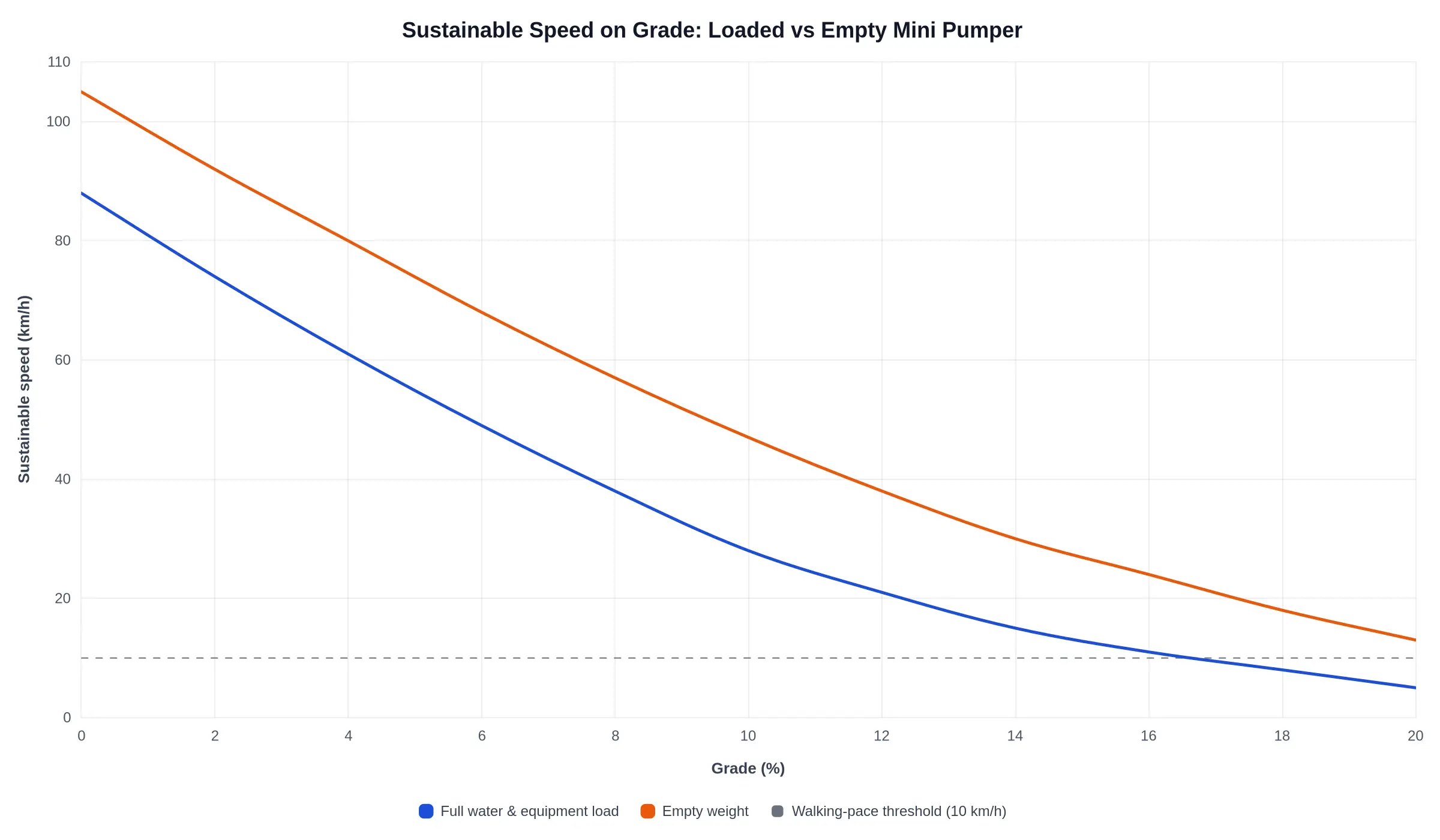
Plotted data (km/h)
| Grade (%) | 0 | 2 | 4 | 6 | 8 | 10 | 12 | 14 | 16 | 18 | 20 |
|---|---|---|---|---|---|---|---|---|---|---|---|
| Full water & equipment load | 88 | 74 | 61 | 49 | 38 | 28 | 21 | 15 | 11 | 8 | 5 |
| Empty weight | 105 | 92 | 80 | 68 | 57 | 47 | 38 | 30 | 24 | 18 | 13 |
What the curves actually tell a purchasing committee
On a rural or wildland response, three things in that table matter.
- The lines are not parallel, and the penalty is worse than the raw gap suggests. At 0% grade the loaded truck gives up 17 km/h to the empty one, about 16 percent of its speed. At 14% grade the gap is 15 km/h, but the empty truck is only making 30 km/h, so the loaded truck has lost half of what the chassis can do. Every extra kilogram of water fights gravity in the same direction as the engine, so load costs more the steeper it gets.
- The loaded curve drops below the 10 km/h walking-pace threshold at roughly 17% grade. Between 16% and 18% the loaded truck falls from 11 km/h to 8 km/h, and past that point a crew on foot outruns the apparatus. On an unmaintained forest track or a wet gravel incline, that is the difference between a truck that reaches the fire and a truck that becomes a logistics problem.
- The empty curve is not the design case. Unladen figures get quoted because they look good in a brochure. The only number worth having is the one measured with a full tank, hose beds packed and four firefighters on board.
Translating the chart into a spec sheet
Speed on grade is the visible symptom of the relationship between tank capacity, rear axle rating and total loaded mass. Put a 2,000 L (528 gal) tank on a compact chassis and you do not just lengthen the fireground duration; you move the entire loaded curve down and to the left. That is why a steep-driveway specification should start from a gradeability calculation at gross vehicle weight, checked against rear axle margin, rather than from a top-speed figure. Departments comparing bodywork and tank sizes across compact small fire trucks should ask each supplier for the loaded figure at 10% and 15% grade specifically, and treat a response that quotes only unladen data as incomplete.
Two calibrations are worth adding to a demo drive. Run the hill loaded, with water on board, and time the climb rather than simply completing it: sustained speed is what determines whether the pump arrives with useful pressure and a cool engine. Then repeat the climb in low range if the transfer case allows it. A lower gear does not change the physics in the chart, but it changes how much of the engine’s torque band is available to hold speed without overheating.
Steep Driveway Access: Gradeability, Angles and Wheelbase
Grade is a number, not an impression. To measure a driveway, park on its steepest segment, hold a straight edge level, and measure the vertical rise over a known horizontal run. Rise divided by run times 100 gives the grade percentage, and percent is not degrees: a 20% grade is about 11.3 degrees, already enough to pull weight off the front axle of a loaded truck. Measure the worst segments separately instead of averaging the whole drive, and look hardest at the gutter approach, the crest where the drive meets the road, and any rapid transition where the grade changes over a short distance.
Where the Chassis Actually Catches
Published gradeability describes tractive ability on one uniform slope. A real driveway adds three geometric constraints, and the lowest of them governs access: approach angle at the front bumper and plumbing, departure angle at the rear step and hose bed overhang, and breakover angle at the crest. Wheelbase sets how these trade off. A long-wheelbase compact fire apparatus puts more mass between the axles, which helps ride and pump packaging but lowers the breakover angle, so the crest becomes the limiting feature long before the slope does. Shorter chassis regain breakover and departure clearance and can be reviewed among light fire truck platforms built on short-wheelbase chassis, though they pitch more sharply under braking and on standing starts. Where the drive continues onto unsealed, rutted or broken ground, compare extreme-terrain access options against the same measured grade rather than a brochure figure.
Three measurements belong on the spec sheet before you sign:
- Breakover angle, taken at the tightest crest with the tank full and tires at operating pressure.
- Approach and departure angles, taken with piping, steps and rear hose trays fitted, since bolt-on hardware usually defines the real number.
- Surface friction, estimated from a wet and a dry stop on the grade, because 25% on polished concrete is not the same duty as 25% on gravel.
Water Load, Center of Gravity and the Standing Start
Tank position is a stability decision. Water carried low and ahead of the rear axle keeps the center of gravity close to the frame and limits the pendulum effect on a slope, while an unsecured or under-baffled load surges rearward on a standing start, unloading the front axle and dulling steering exactly when the driver needs it. Baffles and transverse dividers slow that migration; axle margin absorbs the remainder. Ask for the loaded center-of-gravity height and the front and rear axle loads at 100% tank capacity, then check them against the rated limits on the grade you have to climb.
Traction, Tires and Differentials
Climbing comes down to rubber and torque delivery. Choose a tire whose load rating matches the loaded axle weight, a tread pattern suited to the surface, and pressures set for the duty rather than for the highway. A locking or limited-slip differential turns a wet or gravel drive from marginal into routine, and single rear wheels with an aggressive tread frequently outperform duals on soft ground because contact pressure is higher.
Descent Control: Engine Braking, Retarder and Exhaust Brake
Descent deserves as much attention as climb. An exhaust brake on a diesel holds a steady speed without heating the service brakes, a transmission retarder does the same more smoothly on longer grades, and torque converter lock-up keeps engine braking effective instead of letting it slip away. Confirm that the retarder can hold a loaded apparatus at a controlled speed on the target gradient, not merely that the feature is fitted.
Ground Clearance for Pump Piping and Rear Steps
Measure the lowest point of the running vehicle, not the frame rail height. Suction and discharge plumbing routed under the body, drain valves and rear step assemblies often hang below the chassis and quietly destroy departure angle. Relocated piping, skid plates and a folding step cost far less than a crushed discharge manifold at the bottom of a lane.
Ask for a loaded demonstration on a measured grade, with a standing start, a crest transition and a controlled descent, so that geometry, traction and braking get proven together rather than on separate days.
Approach, Departure and Breakover Angles: The Three Numbers That Decide Whether Your Mini Pumper Reaches the Fire
Departments rarely lose a purchase on pump capacity. They lose it on the last forty feet of gravel lane, ranch track or switchback service road. A compact pumper can be perfectly specified on paper and still scrape its rear step every time it backs into the bay, or high-center on the crown of a driveway crest six months after delivery. Angles are the cheapest thing you will measure and the most expensive thing to fix afterward.
The schematic below strips the geometry down to line work: one silhouette on a slope, three annotated arcs, and a small grade triangle for reference.
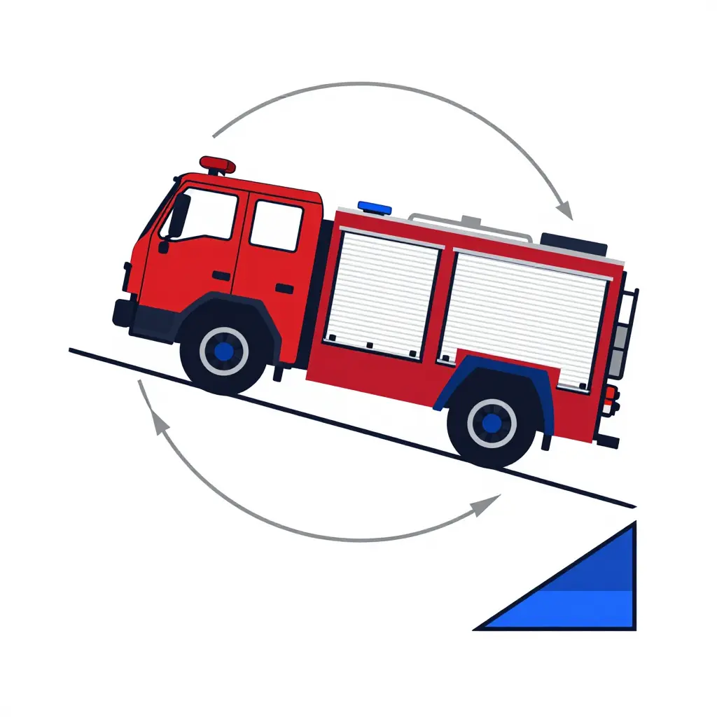
Figure 1: Approach angle at the front bumper, departure angle at the rear step, breakover angle under the wheelbase, and a grade-ratio triangle for scale.
Approach angle: the front bumper test
The approach angle is the angle between the ground plane and an imaginary line drawn from the front tire contact patch up to the lowest forward point of the vehicle. Every inch of front overhang costs degrees, because the arc sweeps from the contact patch, not from the axle center.
On mini and quick-attack pumpers the front bumper usually carries the most vulnerable hardware: pump intake plumbing, a front suction screen, winch fairleads or a bumper-mounted monitor. Those fittings sit low and forward, exactly where the arc is tightest. A builder who tucks the bumper in and lifts the plumbing a few inches can buy back three to five degrees without touching the wheelbase.
Departure angle: the rear step test
The departure angle is the mirror image at the back: a line from the rear tire contact patch up to the lowest rearmost point, usually the rear step, hose bed rear panel, dump valve body or tow hitch. This is the angle that fails first on rural properties, because it is judged while reversing up a grade with the tail low and the driver watching a spotter in a mirror.
Rear-mounted dump chutes, booster reel brackets and folding steps all subtract from the number. On hilly districts, specify a recessed or flip-up step and a protected dump valve rather than assuming the standard body will clear. If your department works this terrain regularly, compare sealed rear-body layouts across the compact fire truck range before the build sheet is frozen: two similar-looking bodies can differ by five degrees or more.
Breakover angle: the number nobody quotes until it is too late
The breakover angle describes the crest. Two lines are drawn upward, one from each tire contact patch, to the lowest point of the chassis midway between the axles, and the arc appears underneath the middle of the wheelbase on the schematic.
Watch the convention here, because two sets of numbers circulate in the industry:
- Off-road convention: the small angle between those two lines. Bigger is better.
- Apparatus convention: the supplementary angle, usually quoted in the 140s to 160s of degrees. Bigger is still better.
Either way the lever is wheelbase. Tank position, subframe depth, driveline routing and the low point of the pump module all set the number, and stretching the wheelbase by a foot to gain rear axle margin quietly costs breakover. That trade-off belongs in the same conversation as axle loading, not in a separate one.
Why a 10% grade and a 20% grade are not the story
Percent grade is rise over run. Converting it to degrees makes it comparable with the angles above:
| Grade | Rise per 100 in of run | Angle from horizontal | What it does to a compact pumper |
|---|---|---|---|
| 10% | 10 in | 5.7 degrees | Comfortable for most bodies; watch the rear step on reverse entry |
| 20% | 20 in | 11.3 degrees | Demands a genuine departure angle margin and a low pump module |
A 20% driveway sounds brutal until you convert it: 11.3 degrees, which most apparatus will climb. What stops a truck is not the slope but the transitions: the short vertical curve at the top of the ramp, the culvert lip, the drainage dish at the apron. A steep grade with a generous crest radius is friendlier than a gentle grade with a sharp break at the top.
How to measure your own station and driveway
- Park the candidate truck, loaded to its wet weight with a full tank, on level concrete.
- Drop a plumb line from the lowest front bumper point, the lowest rear point and the lowest mid-wheelbase point to the ground.
- Measure heights and horizontal offsets, then check the arcs with a digital angle finder against a 10 ft straightedge laid under each tire.
- Repeat at the actual site, with a spotter, on the steepest approach and the steepest reverse entry, loaded rather than empty.
- Put those three numbers in writing on the specification sheet, alongside rear axle margin and tank baffle design.
Verification Sequence Before You Sign
Work through these in order, and do not approve the purchase order until each item is documented in writing.
- Obtain certified axle-by-axle weight tickets for the completed unit with a full water tank, full fuel, the specified hose load and crew positions occupied, issued by a calibrated scale.
- Confirm the rear GAWR stamped on the certification label against the measured rear axle load, and confirm that each tire’s load rating at operating inflation pressure exceeds the measured corner weight by an adequate engineering margin.
- Verify the loaded water weight by checking tank capacity in gallons against 8.34 lb per gallon, then adding tank, baffle, pump and plumbing weight to the chassis tare weight.
- Request tank baffle drawings and weld test records, including baffle spacing, baffle-to-shell attachment detail, and dye-penetrant or pressure test results for every welded seam.
- Calculate gradeability in the lowest gear for the steepest access point in the response area, using loaded weight, engine torque curve, transmission and axle ratios and tire rolling radius rather than the brochure gradient claim.
- Specify the minimum approach, departure and breakover angle limits your response area requires, then measure the delivered apparatus against those figures on level ground with the suspension at ride height.
- Require a loaded demonstration climb and descent of the steepest grade on your access route, witnessed by your committee, with the tank at operating level and a member positioned at the top and bottom.
- Confirm braking and retarder performance on that same grade, including service brake fade behavior, parking brake holding capability, and automatic transmission retarder engagement on descent.
- Verify pump performance at a full tank, recording rated pressure and flow, priming time, and any cavitation or aeration observed as tank level drops toward one quarter.
- Record serial numbers and warranty terms for the tank and suspension: shell warranty duration, baffle coverage, proration clauses, and the service location that will perform warranty work.
Departments evaluating compact mini pumpers can attach this sequence to the bid specification as a written acceptance checklist, so every weight, angle and test result is verified by measurement rather than assumption.
Table 1. Mini Pumper Configuration Comparison – typical engineering ranges across three chassis classes for compact fire apparatus, to be used as a screening tool before weight verification.
| Specification | Configuration A: Light Commercial Chassis | Configuration B: Medium-Duty Chassis | Configuration C: Industrial/Wildland Chassis |
|---|---|---|---|
| Water tank capacity | 300-500 US gal (1,135-1,890 L) | 500-750 US gal (1,890-2,840 L) | 250-750 US gal (945-2,840 L) |
| Rear GAWR | 13,000-15,000 lb (5,900-6,800 kg) | 21,000-23,000 lb (9,525-10,430 kg) | 15,000-24,000 lb (6,800-10,885 kg) |
| Estimated rear axle load at full tank | 10,500-13,000 lb (4,760-5,900 kg) | 18,000-21,500 lb (8,165-9,750 kg) | 12,000-20,000 lb (5,440-9,070 kg) |
| Rear axle margin | 8-18% | 6-15% | 10-22% |
| Tank baffles (number and orientation) | 2-3 vertical transverse baffles, full height | 3-4 vertical transverse baffles, often one longitudinal | 4-6 transverse baffles plus longitudinal divider, cross-baffled |
| Wheelbase | 165-193 in (4,190-4,900 mm) | 175-220 in (4,445-5,590 mm) | 150-178 in (3,810-4,520 mm) |
| Approach angle | 22-28 degrees | 20-26 degrees | 30-40 degrees |
| Departure angle | 18-24 degrees | 16-22 degrees | 24-32 degrees |
| Estimated gradeability at full load | 28-38% | 25-32% | 40-55% |
| Typical pump output | 750-1,000 gpm (2,840-3,785 L/min) | 1,000-1,500 gpm (3,785-5,680 L/min) | 500-1,250 gpm (1,890-4,730 L/min) |
Note: All figures are indicative ranges only. Actual tank size, axle ratings, baffle layout, angle and gradeability values vary by bodybuilder, chassis specification, water and foam load, hose and equipment complement, and tire selection. Confirm every configuration against certified weight tickets and the manufacturer’s rated GAWR before purchase.
Matching Chassis and Body Configuration to the Mission
Chassis selection is an exercise in margins. The rear axle margin left once water, foam, pump, hose, tools and crew are loaded decides how much tank a frame can carry before braking balance, tire loading or warranty coverage suffers. Baffle arrangement then sets body length: a tank with correctly spaced transverse baffles controls surge on a part-full load, and each extra baffle or wider compartment pushes the rear overhang out and moves the wheelbase.
Gradeability follows the same arithmetic. A sustained grade needs a power-to-weight ratio, gearing and traction package sized for the loaded vehicle, plus enough approach and departure angle to clear the transitions at the top and bottom of the slope. Short-wheelbase cab-over layouts work at constrained sites; longer conventional frames gain highway stability and lose maneuverability.
Four chassis families, four duty profiles
Light commercial cab-over. Narrow-track cab-over frames turn tightly and fit narrow lanes, gate openings and tight yards, and suit a compact pumper carrying roughly 300-500 gal with a single-stage pump. Frame rail capacity and rear axle rating set the ceiling, so buyers should confirm residual axle margin with the tank full and the hose bed loaded. Compare these against the wider range of cab-over and conventional fire fighting truck chassis before fixing body length.
Medium-duty chassis. Where tank volume and pump capacity matter more than footprint, a medium-duty frame carries 500-750 gal baffled tanks, a two-stage pump and a deeper hose body. The higher GVWR permits dual rear wheels and a longer body; gradeability is then governed by engine torque curve and transmission ratio rather than by traction alone.
Industrial specification. Plant, terminal and refinery duty adds foam proportioning, protected electronics, static grounding and extended-duty cooling to an industrial fire truck platform, together with heavier axle ratings and body mounts that support monitor loads and long-duration pumping at fixed positions.
All-terrain units. Wildland and off-road response calls for four-wheel drive, generous ground clearance, single or super-single rear tires and a short rear overhang. A wildland fire truck typically pairs a modest tank with CAFS or a high-pressure pump, which keeps water weight, and the brake demand on descent, inside the chassis envelope.
| Chassis family | Typical tank / pump | Rear axle margin focus | Access and gradeability notes |
|---|---|---|---|
| Light commercial cab-over | 300-500 gal, single-stage | Confirm margin with full tank and loaded hose bed | Tight turning circle, narrow track, low step-in height |
| Medium-duty | 500-750 gal, two-stage | Dual rear wheels and rated axle for full static load | Longer body, higher GVWR, torque-led climbing |
| Industrial specification | Foam-capable, monitor-fed | Axle and mount ratings for monitor and long pump duty | Stable at fixed plant positions, heavy frame |
| All-terrain | Small tank with CAFS or high-pressure | Margin retained for 4×4 driveline and tire mass | High clearance, short overhang, traction on loose grade |
Converting the profile into a specification
Record the site data before the chassis is specified: worst-case grade, aisle width, gated or bridged access, and the water volume the first-arriving unit must deliver on its own. Where a pumper also has to carry rescue tools, pair it with a dedicated emergency rescue vehicle instead of overloading the rear axle. Budget weight for deck guns, hose, suction and portable fire fighting equipment, so the delivered truck leaves usable margin rather than spending its rating on day one.
Frequently Asked Questions
How much rear axle margin is enough on a mini pumper?
Plan for a minimum 10 percent reserve between the fully loaded rear axle weight and the rear GAWR on the chassis placard. Scale the apparatus with water, foam, hose, tools and seated crew at 250 lb (113 kg) per riding position, then compare each measured axle load against its rating. A rear axle margin below 10 percent leaves no allowance for added equipment and pushes weight onto the rear springs, which reduces roll stability. Buyers comparing mini pumper fire trucks for sale should require the axle-load calculation in writing before a purchase order is issued.
Do small water tanks still need internal baffles?
Yes. Compact apparatus tanks need baffles because a 300 gal (1,136 L) water load is roughly 2,500 lb (1,134 kg) of moving mass. Transverse baffles, normally spaced at 24 in to 36 in (610 mm to 900 mm) on center, limit the slosh-induced load transfer that can shift 30 to 50 percent of the liquid mass during braking or cornering. Without them, the surge degrades roll stability and lengthens stopping distance on wet pavement.
Can a mini pumper with a full tank climb a steep driveway?
Yes, provided the chassis is specified for the grade. A 4×4 mini pumper carrying 500 gal (1,892 L) adds about 4,170 lb (1,891 kg) of water plus the tank shell, and gradeability at that weight is governed by tractive effort rather than engine output. Most vocational 4×4 chassis hold a 20 to 25 percent grade (11.3 to 14 degrees) at gross weight in first gear, low range, when the drive tires are correctly loaded.
How should gradeability be verified before purchase?
Run the demonstration with the tank at 100 percent on the steepest grade the department will actually respond on, measured with a digital inclinometer or survey level. The test must include a standing start from the base of the slope and a full-stop restart at mid-grade to prove startability, not just momentum carry-through. Ask the builder for the gradeability calculation, tractive effort at the drive wheels divided by gross vehicle weight minus rolling resistance, and tie that steep driveway access data directly to the purchase contract as a signed test report.
How is tank baffle construction inspected and documented?
Review the tank build record for baffle spacing, baffle-to-shell weld schedule, material certificates such as 5052-H32 aluminum at 3/16 in (4.8 mm), and the tank serial number. Physical inspection covers continuous welds at baffle-to-shell and baffle-to-baffle joints, verified by dye-penetrant testing, plus a hydrostatic or air-pressure leak test documented at 3 to 5 psi (21 to 34 kPa). File the photographs, weld procedure specification and test certificate with the delivery paperwork so the record survives crew turnover and future resale.
How does a mini pumper differ from a slip-on or quick-attack unit?
A slip-on is a skid-mounted pump-and-tank module loaded onto a pickup or flatbed chassis, and a quick-attack unit is a light first-response truck carrying 100 to 300 gal (379 to 1,136 L) with a small pump. A mini pumper is purpose-built on a dedicated commercial or 4×4 chassis with an integrated 250 to 750 gpm (950 to 2,840 L/min) pump, a 300 to 750 gal tank, NFPA 1901-compliant hose beds and seating for a full crew. That integrated build, with unified frame mounting, engineered axle loading and factory baffling, is what separates it from a bolt-on skid unit.
Bringing the Three Specifications Together
Rear axle margin governs legal payload and braking stability, tank baffles govern vehicle control and structural life, and gradeability governs whether the apparatus reaches the incident at all. A deficiency in one cannot be offset by strength in the other two, which is why they belong in one set of acceptance criteria rather than in separate boxes on a quotation sheet.
Departments moving beyond a standard body, including specialized fire truck configurations, should treat the three numbers as the criteria that shape the build: laden rear axle weight against rating with full water and foam load, crew and equipment aboard; baffle count, placement and weld detail for the tank volume ordered, with slosh-test documentation; and startability and grade-holding on the steepest driveway or access track in the response area, measured at real payload instead of bare-chassis claims. All of it belongs in the contract documents, verified in writing before the order is placed.