What an Airport Fire Truck Factory in China Actually Builds
An airport fire truck, or ARFF (Aircraft Rescue and Fire Fighting) vehicle, has one job: reach a burning or disabled aircraft within minutes and put very large volumes of foam and water onto it at high pressure. What separates it from a standard fire appliance is how much it has to do at once. It must accelerate hard, sit low, carry a heavy water and foam load over rough ground, and deliver a correctly proportioned foam blanket on the first pass, because a live runway offers no second attempt.
Work at an ARFF plant divides into two disciplines. Chassis integration is mounting the body, water and foam tanks, fire pump and roof monitor onto the chassis with the weight distribution and driveline coupling that keep the finished truck stable at speed, in sharp turns and under hard braking. Foam system testing is proving proportioning accuracy, expansion ratio and discharge performance on the test pad before delivery, so the system produces the blanket and the throw the specification promises.
CIMC Tianda, with more than 20 years in firefighting and rescue equipment and operations across 75 countries, treats both disciplines as the measurable part of factory capability. They are also the two things buyers of airport fire trucks can check without taking a factory’s word for anything.
Chassis Integration: Matching the Chassis to the Mission
Bolting a tank onto a commercial truck does not produce an ARFF vehicle. Chassis integration is the engineering step where the chassis and the firefighting body are designed as one load path, one power system and one electrical network. It decides whether the numbers on the spec sheet hold at the airport or start drifting on day one.
The weight budget comes first
A liter of water weighs about a kilogram, and foam concentrate slightly more, so the full tank load is a known figure before anyone designs a body. That figure, plus fuel, crew and equipment, has to fit inside the gross vehicle weight rating, and every axle carries its own limit, which is why the tanks sit over or just behind the rear bogie rather than wherever they happen to fit.
| Component | What it drives in the design |
|---|---|
| Water and foam tanks | Gross weight, rear axle load, center of gravity height |
| Pump and PTO | Engine rating, driveline angles, cooling capacity |
| Roof or bumper monitor | Structural reinforcement at the mounting point, reaction loads |
| Hose, tools and rescue gear | Compartment layout, side-to-side balance |
| Fuel and crew | Legal axle limits, braking and tire ratings |
A factory that hands over an axle-by-axle weight ticket for the completed truck has shown that the integration happened. Airports and their insurers ask for that ticket at acceptance.
Frame rails, subframe and the power take-off
Factory integration usually adds a reinforced subframe between the rails and the body, so the concentrated loads from the pump, the monitor base and the tank baffles spread along the frame instead of resting on a few bolt holes. The power take-off is the joint that has to be engineered rather than adapted: it takes torque off the transmission to drive the pump, and driveline length, universal joint angles and support bearings decide whether it runs smoothly or shakes itself into premature wear. Pump-and-roll capability depends on that coupling being right.
Torsional flexibility and a low center of gravity
A chassis flexes as it crosses ramps and rough apron surfaces, and the body must not fight it. Three- or four-point mounting lets the frame twist while the body stays straight, which is what keeps tank walls and compartment seams from cracking over years of service. Where the mass sits matters just as much: a low center of gravity improves rollover resistance and keeps weight transfer predictable under hard braking, when a full water load is pushing forward.
Routing, protection and climate
Harnesses and piping run clear of exhaust heat, moving linkages and sharp edges, with supports and chafe protection at regular intervals. At coastal or humid airports the specification should call for galvanized or coated subframes, stainless or coated piping, sealed connectors and drainage paths, because salt air and condensation attack a truck from the inside out. Buyers comparing heavy-duty fire truck chassis solutions can ask which of those items are standard and which are extra.
All four are verifiable before you sign: weight certificates, driveline drawings, mounting design and a written corrosion plan.
The Chassis Integration Workflow
Eight steps separate a bare commercial chassis from the structural platform of a finished truck, and each one leaves a document behind. The sequence below is the one used for aircraft rescue fire fighting vehicles; tank mounting, pump plumbing and foam testing all rest on what happens in it, so it doubles as an audit checklist.
The eight steps in order
- Incoming chassis inspection and dimensional verification. Confirm that the delivered chassis matches the purchase order in model, wheelbase and gross vehicle weight rating. Measure the key frame dimensions against the engineering drawing before any cutting or drilling begins.
- Documentation of chassis and driveline specifications. Record engine data, transmission ratios, axle ratings, power take-off (PTO) output and frame rail section. These figures become the reference baseline for weight calculations and later approval documents.
- Frame preparation and reinforcement. Clean and treat the frame rails, then weld or bolt the reinforcement sections the tank and pump loads require. Correct reinforcement is what stops the frame flexing under the weight of a full water load.
- Driveline and power take-off coupling to the fire pump. Align the PTO with the pump driveshaft, set the coupling angles and verify the drive path. This step decides whether the pump reaches its rated flow at the required pressure.
- Mounting of water tank, foam tank, and equipment lockers. Install the tanks on their sub-frame with the specified flexible mounts, then fit lockers and secure every attachment point. Order matters: tanks go on first, so piping and locker placement follow the verified weight distribution.
- Electrical harness, control panel, and lighting installation. Route the wiring harness along protected paths, install the pump control panel, and fit emergency and scene lighting. Continuity, insulation and function checks follow each circuit as it goes in.
- Weighing, axle-load verification, and alignment check. Weigh the completed vehicle by axle and compare the result with the approved load plan, then check wheel alignment to correct for the change in ride height.
- Factory road and brake test before foam system work begins. Run the vehicle on the factory test route and check braking, steering response and driveline behavior under load. Foam work starts only after the platform has passed.
Signed photographs at each of the eight steps leave an auditor with a record of how the work was done, which is worth more than an assurance that it was done properly.
On the finished chassis the modules sit in a fixed order: cab block, paired water and foam tanks, pump and plumbing package, rear equipment bay, with the roof monitor above the pump. Tank splits and body styles change between models, which this overview of airport fire trucks sets side by side, but the front-to-back sequence does not.

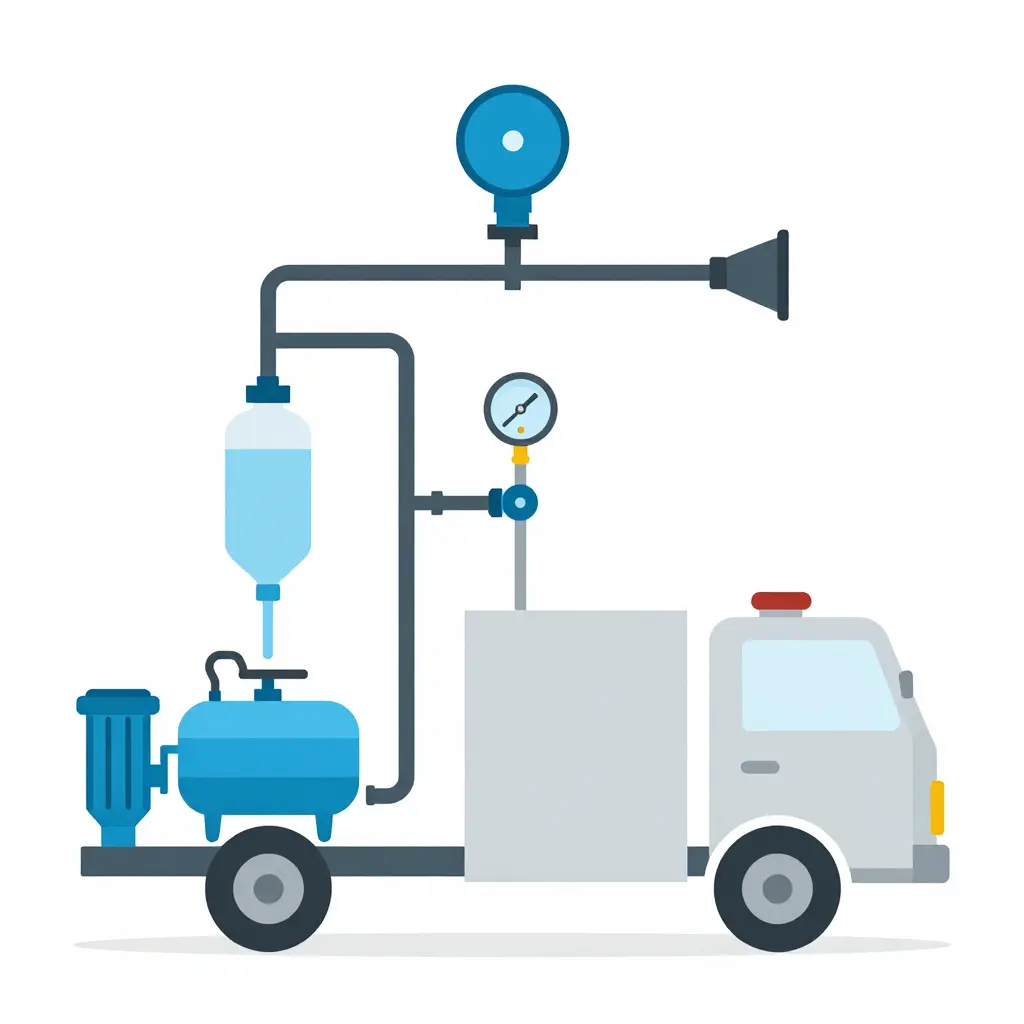
Schematic reference: module arrangement on an integrated airport fire truck chassis, front to rear.
Foam System Testing: What the Factory Measures
The foam system does not leave the factory as a list of components on a drawing. It is run as a working system with instruments attached, and every result is written down. Each test below produces a number you can compare with a target, and each number has a cost consequence for the operator who signs for the truck.
1. Foam proportioning accuracy at rated induction rates
This is the core measurement. The truck runs at its rated flow on both the 3% and 6% settings, and a sample of solution is drawn downstream of the proportioner and analyzed for actual concentrate concentration. A 3% setting that delivers 2.2%, or a 6% setting that delivers 7.1%, is a real result and is recorded as such. Under-dosing produces a weaker blanket that collapses early. Over-dosing spends concentrate faster than the tank capacity suggests and shortens the time the truck can keep working.
2. Expansion ratio of the finished foam
The finished foam is collected and its volume compared with the volume of solution that made it. The ratio describes the foam’s structure, wet and low-expansion or drier and medium-expansion, and it tells a buyer how far a tank of concentrate will spread across a spill or a running fuel fire.
3. 25% drain time
A sample is left to stand and the time taken for a quarter of its liquid to drain out is recorded. Drain time is the standard measure of blanket durability. A longer drain time generally means the blanket holds its water and reseals after disturbance, which matters on a long incident when the foam has to sit on the fuel surface.
4. Application rate through the roof monitor and bumper turret
The truck discharges through the roof monitor and the bumper turret separately, and the delivered flow from each outlet is measured. That is what each nozzle actually puts on the ground at the operating pressure, as opposed to what the pump is theoretically capable of. Application rate per unit area decides whether the truck can put a blanket down fast enough on a realistic fire scene.
5. Sufficient discharge duration under continuous operation
With tanks at rated capacity, the system runs continuously at rated output and is timed. The result is a working duration in minutes before resupply, and for an airport fire truck that figure belongs in the response plan, so it should come from a stopwatch rather than an estimate.
6. Performance when switching between water and foam
The system is cycled through water, then foam, then water again. The checks are that the proportioner responds cleanly at each change, that the pump re-primes without hesitation, and that no air enters the line at the moment of switching. Poor switching shows up on the fireground as a slug of plain water where foam was expected.
7. Verification of CAFS output, where fitted
On vehicles with compressed air foam, the air-to-solution ratio is set and verified, and the discharged foam is inspected for consistent texture at the branch. CAFS output cannot be inferred from the compressor rating: the finished foam is measured, because the air ratio sets both the reach of the stream and how long the blanket lasts.
Why the testing happens before delivery
Every check above runs at the factory, on the completed vehicle, before shipping. What the buyer receives is a record of measured performance (flow, concentration, expansion, drain time, duration) rather than a sheet describing what the design intends to do. That difference shows up when a fleet is specified, when tender documents have to be answered with evidence, and when a machine is accepted against a contract. The same test data can be requested on each model in the foam fire truck range and compared like for like.
| Test | What is measured | Commercial relevance |
|---|---|---|
| Foam proportioning accuracy | Actual vs target concentration at 3% and 6% | Concentrate consumption and blanket strength |
| Expansion ratio | Foam volume per unit of solution | Coverage achievable from each tank load |
| 25% drain time | Time for a quarter of liquid to drain | Blanket durability on long incidents |
| Application rate | Delivered flow at monitor and bumper turret | Speed of blanket establishment |
| Discharge duration | Continuous run time at rated output | Working time before resupply |
| Water-to-foam switching | Proportioner response and pump re-priming | Consistency of foam at the branch |
| CAFS output | Air-to-solution ratio and foam texture | Stream reach and blanket persistence |
Testing the assembled system is what turns a folder of component certificates into a performance record for one specific vehicle.
Foam System Test Parameters and Typical Factory Acceptance Criteria
The table collects the checks Chinese airport fire truck builders usually run on the foam system, with the ranges you should expect to find in a test report. Treat the figures as reference points rather than contractual guarantees: the real numbers follow the chassis, pump, monitor and concentrate you specify.
| Test Item | How It Is Measured | Typical Factory Acceptance Criterion | Why It Matters to Buyers |
|---|---|---|---|
| Foam proportioning accuracy (3% and 6% induction) | Flow-meter comparison of foam concentrate versus water at several flow rates | Typically within ±10% of the set ratio across the rated flow band | Wrong ratio either wastes expensive concentrate or weakens the blanket |
| Expansion ratio | Foam sample collected in a graduated vessel, compared with solution volume | Typically 6:1 to 8:1 for AFFF types, up to about 10:1 for some concentrates | Sets how much finished foam you get per liter of premix |
| 25% drain time | Time for 25% of the liquid to drain out of a foam sample | Typically 3 to 5 minutes or longer, depending on concentrate | Longer drain time means the seal holds against hot metal |
| Monitor and turret application rate | Flow rate and throw distance measured at rated pump pressure | Typically 1,500 to 3,000 L/min at 8 to 10 bar, throw of roughly 60 to 75 m | Determines whether you can reach a fuselage from a safe standoff |
| Continuous discharge duration | Full-rate discharge from monitor until the tank runs dry | Divide tank volume by monitor rate: a 9,000 L tank through a 3,000 L/min monitor gives about 3 minutes | Defines the real knockdown window at an incident |
| Water-to-foam switchover response | Time from valve actuation to foam reaching the branch or monitor | Typically under 5 seconds, often 2 to 4 | Every second of delay is water on the fire instead of foam |
Ask each supplier for measured values rather than catalog figures, and for the test record of the exact unit you are buying. If the platform is still being shortlisted, look through the range of airport fire trucks built on integrated chassis before the foam specification is locked in, because monitor size, tank layout and pump drive all move the numbers above.
Documentation and Handover: Why the Paper Trail Is a Purchasing Asset
An airport fire truck should arrive at handover with a document package that shows what was built, how it performed on the test pad, and exactly what the buyer now owns. That package is part of the purchase price, not paperwork to file and forget.
The factory test report: recorded proportioning and discharge data
The factory test report is the core document. It records proportioning ratios at several flow rates, pump discharge pressure and flow, monitor reach and nozzle performance, and the results of the foam blanket checks, each figure dated, signed and tied to the chassis and body serial numbers. The values on the page can then be matched to the truck standing in your bay.
Calibration, weighing, and as-built records
Pump and monitor calibration records show that discharge instrumentation and monitor travel were checked against reference equipment, which gives your workshop a known baseline for later service. Axle-load and weighing certificates show how the finished vehicle distributes weight across each axle, the figure that governs road-use legality, tire and brake life, and stable braking on the runway.
As-built drawings and piping diagrams go beyond the design. They show the final pipe routing, valve positions and foam concentrate line connections, which saves hours on repairs, retrofits or the addition of a second agent system.
Control systems, training, and spare parts
The electrical and control manual should carry wiring schematics, control logic and fault codes, so a technician can diagnose a fault instead of guessing. Operator and maintenance training, in the classroom and hands-on at the truck, should be documented with attendance and competency records. The recommended spare parts list closes the set, with part numbers and suggested stock levels for the items most likely to wear.
Warranty terms tied to documented test results
A warranty is strongest when it references the recorded test values. If a pump, monitor or proportioning complaint comes up, both sides compare current performance with the factory baseline instead of arguing about expectations, and a clause that would otherwise be a statement of intent becomes something both parties can measure against.
| Handover document | What it proves | Who relies on it |
|---|---|---|
| Factory test report | Proportioning and discharge recorded during foam system testing | Buyer, auditor, insurer |
| Pump and monitor calibration records | Instrument and monitor accuracy verified | Maintenance team |
| Axle-load and weighing certificates | Compliance with chassis and road load limits | Fleet engineers, regulators |
| As-built drawings and piping diagrams | Installed configuration, not just design intent | Workshop, upgrade planners |
| Electrical and control system manual | Schematics, logic, fault codes | Technicians |
| Training records | Crew competency at handover | Safety officers, HR |
| Recommended spare parts list | Part numbers and critical stock levels | Procurement |
| Warranty terms | Baseline values used in claims | Owner, legal |
Where these records pay for themselves
A fleet compliance audit is the first place. Aviation authorities, insurers and municipal safety inspectors ask for evidence of performance testing, calibration and load compliance, and a binder that answers those questions in one sitting shortens the review. The second is resale or fleet expansion, where a documented test and service history supports a higher asking price and faster due diligence, because the next owner can read the truck’s condition in numbers rather than in adjectives.
Before signing, ask for a sample handover package, and look through the full fire fighting truck catalog to see how configuration choices change the documentation you will receive. A factory that can produce that file on request is usually a factory that tests what it ships.
Foam Proportioning Accuracy: The Number That Decides Whether the Foam Works
The foam has to be right at the nozzle, not in the tank. A 3% AFFF concentrate works inside a narrow band. Run it lean and the blanket breaks down, vapor escapes and the fire re-ignites. Run it rich and concentrate disappears faster than the refill plan allows, leaving a sticky film on the runway. Factory testing is where the proportioner, pump, pipework and controller are shown to agree with each other at real flow rates.
What a Proportioning Test Actually Measures
Most ARFF trucks use a balanced-pressure proportioner or an electronic foam injection controller. Each architecture has its own error sources:
- Pump wear and speed drift — a pump delivering 2% less water than the flow meter expects shifts the ratio immediately.
- Pressure imbalance between the foam and water lines — small back-pressure differences at the venturi change the induction rate noticeably.
- Pipework losses — elbows, reducers and long runs cost pressure that the proportioner has to compensate for.
- Controller calibration — flow meter scaling and K-factor need verifying, not assuming.
The errors stack, so the only honest answer comes from measuring the finished mixture: sample at the nozzle, weigh it or run it through a refractometer, and compare the result with the target.
Reading the Test Data
Factory acceptance reports usually plot a target line and a measured line across several runs, with the tolerance window drawn in so the reader can see whether the system stayed inside it.
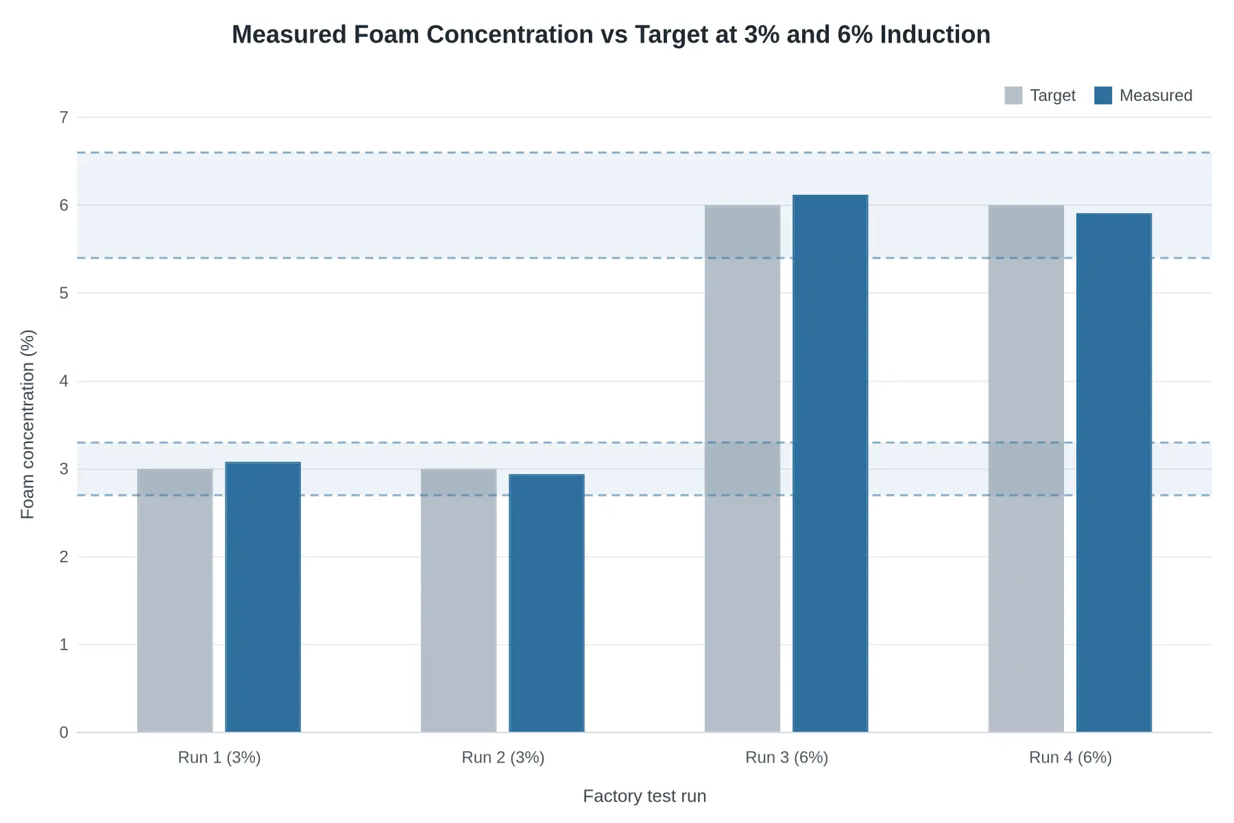
Illustrative data based on common factory test benchmarks. It reflects typical acceptance-test patterns, not the performance claim of any specific product.
Four bars on the left cover the 3% setting, four on the right cover 6%. On 3%, the measured 3.08% and 2.94% sit inside a ±10% window; on 6%, 6.12% and 5.91% do the same. What matters for a buyer is not that every run is perfect but that the deviation is small, repeatable, and on the correct side of the tolerance band at both flow rates.
The Tolerance Question Buyers Should Ask
Suppliers write tolerances in different ways, and the wording changes the comparison when two quotations are side by side.
| Reference | Typical tolerance wording | Practical effect |
|---|---|---|
| Relative to target | ±10% of the set concentration | At 3% this allows roughly 2.70% to 3.30% |
| Percentage points | ±0.3 percentage points | Tighter at high induction settings |
| Test-standard based | Fixed window from the applicable acceptance standard | Best for like-for-like comparison |
Whichever wording you meet, ask for the raw sample results, the flow rate at which each sample was taken, and the ambient water temperature. A proportioner that holds 3.0% at rated flow can drift once a second monitor opens or the flow drops, so a serious acceptance test walks the system through at least three flow points (low, rated and maximum) at each induction setting.
Where the Chassis Integration Comes In
Accuracy is never only a proportioner question. The chassis decides how much engine power can go to the pump, how steady PTO speed stays under load, and how much vibration the foam tank and pipework must survive on a rough taxiway. On a properly integrated aircraft rescue chassis, pump drive and foam system are specified together, so the flow meter sees a stable reference instead of a fluctuating one. When the driveline and the firefighting package are matched only on paper, deviation tends to widen at maximum flow, which is when the crew needs the foam most.
A Simple Checklist Before You Sign
- Ask for the concentration test record at three flow rates per induction setting, not one.
- Confirm the sample method (refractometer, conductivity or weighing) and the calibration date of the instrument.
- Check whether the tolerance is expressed as a percentage of target or in percentage points.
- Verify that both 3% and 6% settings were tested, plus any CAFS or dry-powder combination if fitted.
- Ask how the system reports a fault: alarm, automatic shutdown or silent drift.
A foam system measured clean on a bench and never verified on the finished truck has not been verified. The test record is also the fastest way to tell a careful builder from a fast one when comparing foam fire truck platforms on integrated chassis.
What the Record Should Show
Proportioning accuracy is a small number with a large consequence, and it is one of the few ARFF specifications you can verify objectively before delivery. Look for repeatable measurements inside a stated tolerance at multiple flow rates, and treat a supplier who cannot produce that record as one who has not finished the job.
What Business Buyers Should Verify Before Ordering
An airport fire truck works for fifteen to twenty years, so the specification you sign is a commitment and the documents behind it are the evidence. Every item below is something a serious factory can produce on request; anything you cannot obtain is a question to keep asking before the deposit leaves your account.
Delivery-day failures usually trace back to one of two places. The first is chassis integration, where an unmatched body-to-chassis pairing reduces payload, braking stability and axle compliance without showing up in the brochure. The second is foam system testing, where a proportioning unit that performs perfectly at one setting can drift far outside tolerance at another. Both are invisible on a spec sheet and obvious in a document trail, so ask for the records and read them against your own operating conditions. If the site has unusual access or hazard profiles, work through special fire truck configurations early, before the chassis is locked in.
Send the same list, word for word, to every supplier so the answers can be compared:
- Confirm which chassis model and gross vehicle weight the body was integrated onto, and request the matching chassis certificate.
- Request the weighing report and per-axle load certificate for the completed vehicle.
- Ask for recorded proportioning data at both 3% and 6%, captured during factory testing.
- Confirm expansion ratio and drain time results for the concentrate you will actually store.
- Request the continuous discharge duration for the roof monitor and bumper turret in writing, not as a range.
- Name the documentation and training deliverables as line items in the contract.
- Verify spare parts availability, quoted lead times and service response terms for your region.
- Ask for the pre-shipment inspection or witness-test report, signed and dated by the responsible engineer.
Score each supplier against the same list and tie the final payment milestone to delivery of those documents. That habit turns a technical comparison into a decision tool and leaves you with contractual leverage long after the truck is parked in your station. Operators running dual-purpose fleets can apply the same discipline to industrial fire truck options.
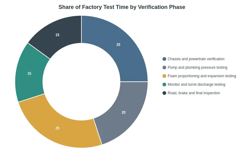
Share of Factory Test Time by Verification Phase
Factory test hours follow risk rather than convenience. The chart splits a typical test window between chassis work, water and foam hardware, and final road checks.
| Verification phase | Share of test time |
|---|---|
| Chassis and powertrain verification | 25% |
| Pump and plumbing pressure testing | 20% |
| Foam proportioning and expansion testing | 25% |
| Monitor and turret discharge testing | 15% |
| Road, brake, and final inspection | 15% |
| Total | 100% |
Half the schedule goes to chassis and foam work, the two areas where a weakness is both expensive and dangerous. The last 15% is not a formality either: a loaded brake and road run is what proves the package behaves as one machine. When a quotation arrives, ask how much of that time is actually run and documented rather than assumed. The same discipline applies across the range, to airport fire trucks and to smaller support units alike.
Note: these percentages are representative of typical factory practice and show relative emphasis, not a fixed rule. Actual allocation shifts with chassis complexity, foam system configuration and the destination market’s approval requirements.
Frequently Asked Questions
How long does chassis integration take from chassis arrival to factory test?
For a standard airport fire truck build, figure on 60 to 90 working days between chassis arrival and the factory acceptance test. The clock starts at incoming inspection, where the frame, axle ratings and PTO provisions are verified against the engineering drawing. Subframe fabrication, tank and pump module mounting, plumbing, wiring harnesses and bodywork then run in sequence, with the last two to three weeks reserved for commissioning. A commercial platform that needs suspension or cooling upgrades sits at the upper end of that range, and a repeat build on a proven design finishes closer to the lower end. Ask the builder to confirm the timeline from purchase-order date, not from contract signature, so the two dates are not quietly conflated.
What level of foam proportioning accuracy should a buyer expect to see documented?
Balanced-pressure and around-the-pump systems are usually documented as holding the set rate within about ±10% across the rated flow band, while electronically controlled direct-injection systems are commonly documented at ±5%. Whatever figure is quoted should be tied to a specific flow range, a stated foam concentrate viscosity and a named test method, not to a single headline number. During foam system testing, ask for raw readings at three or more flow rates instead of a pass or fail line on a summary sheet. Induced concentrate volume against measured water volume, with calibration dates for the flow instruments, is far more useful at the evaluation stage than a percentage on its own.
Can a commercial chassis be adapted for airport fire and rescue duty, and what changes are required?
Yes, and it is a common route when acquisition cost or local service support is the deciding factor, but the adaptation is more than a body swap. Typical changes are frame reinforcement and added cross members, uprated springs and shock absorbers, larger cooling and braking packages, an engine-driven or transmission PTO for the pump, and revised axle load distribution to keep the completed vehicle inside the chassis manufacturer’s ratings. Electrical load management, heat shielding around the pump bay and a roll-over protection structure for the crew cab usually come into it as well. Airfield duty means short, heavy acceleration runs and long stationary pumping periods, so compare the finished specification against a purpose-built airport fire truck before approving the conversion.
What documentation should accompany a factory-tested airport fire truck?
A complete handover pack normally holds the factory acceptance test report, pump performance curves plotted against measured flow and pressure, the proportioning test sheets, and CAFS output records where that system is fitted. Beyond performance data, expect pressure test certificates for tanks and pipework, electrical insulation and earth continuity results, weld inspection reports, paint thickness readings, and a weight certificate for the completed vehicle. You should also receive the chassis OEM warranty documents, operation and maintenance manuals in your preferred language, a spare parts list, and any third-party or classification-society inspection reports. Check that the serial numbers on the certificates match the serial numbers on the unit that arrives.
How does CAFS output testing differ from standard foam proportioning testing?
Proportioning testing answers one question: is the correct volume of concentrate being induced into the water stream at each flow rate? CAFS testing goes further, because compressed air is injected downstream and the quality of the finished foam depends on how well that air is sheared into the solution. Testers therefore measure expansion ratio, 25% drainage time, and discharge pressure and throw distance at the nozzle, and they record the air-to-solution ratio across the working flow range. Pressure losses in the hoseline change the delivered foam, so readings taken at the pump panel alone are not sufficient and have to be confirmed at the nozzle. Both test types should appear as separate, clearly labeled sections in the acceptance documentation.
What a Factory Visit Should Confirm
A buyer assessing an airport fire truck factory in China is really checking two things: whether the driveline and body were engineered as one unit, and whether the foam system was proven on a test stand rather than described on a datasheet. Both leave documents behind, which is what makes them checkable before the deposit is paid. Ask for the weight and driveline file, watch a proportioning run with your own instruments, and read the handover package. Brochure language, showroom finish and delivery promises do not survive that inspection.
CIMC Tianda, operating across 75 countries with more than 20 years in firefighting and rescue equipment, provides these verifications as standard practice rather than as extra requests, and its airport fire trucks ship with the same documentation set.
What a factory can show on paper and on the test stand is the closest thing a buyer gets to proof before the truck is standing on a runway.