Design Freeze Milestones in Custom Fire Apparatus Projects
A custom fire apparatus passes through a sequence of design freeze milestones, and each one narrows what your department can still change. Specification lock comes first: it fixes pump rating, tank capacity, axle rating targets, and the NFPA performance criteria before engineering starts.
Inside the Freeze Gate Sequence
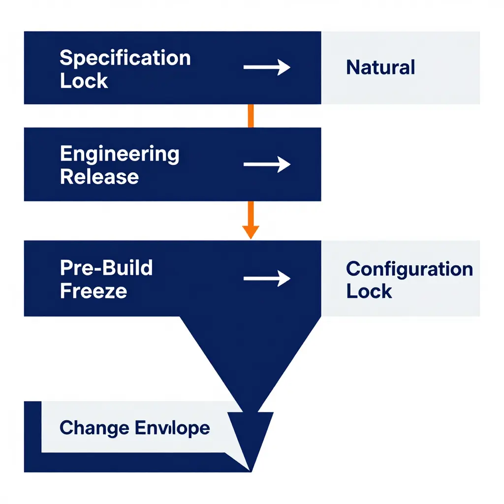
After specification lock comes engineering release, where the builder validates pump module fit, PTO placement, and weight distribution against the chassis. The pre-build freeze follows, confirming the chassis/pump-module interface on a configurable platform such as the T-Line fire apparatus. The final configuration lock, also called the as-built release, closes the envelope for good.
| Gate | What Locks | Remaining Change Envelope |
|---|---|---|
| Specification Lock | Pump rating, tank, axle targets | Broad |
| Engineering Release | Pump module fit, weight | Moderate |
| Pre-Build Freeze | Chassis/module interface | Narrow |
| Final Release | As-built configuration | Closed |
Why Skipping a Gate Compounds Risk
Each milestone doubles as a procurement checkpoint. Let one slip and a wheelbase or axle change forces re-engineering, delivery slips, and the contract may trigger change orders. Tie payment and delivery clauses to the milestones themselves so that slippage stays visible.
Pump Module Fit: Interface Compatibility and Envelope Constraints
Before the design freeze takes effect, the pump module fit has to be validated against every chassis interface, not signed off as a standalone assembly. The module mounts to reinforced frame rails through four to six isolator pads, and bolt patterns, pad height, and shim stacks must be frozen together so the installation does not deflect the rails or misalign the driveline.
The PTO or split-shaft drive has to mate to the transmission output at the correct spline count and driveline angle, with operating angles held inside tolerance to keep vibration down. Waterway sizing follows the rated flow, and the intake and discharge manifolds must clear crossmembers and fuel tanks while preserving the required bend radii and pump inlet geometry. See fire truck pump capacity for how manifold sizing tracks the intended rating.
Plumbing needs support intervals at defined spacing to absorb chassis flex, and hose bed clearances must let stacked hose sit without chafing on the module or body panels. Engineers verify clearance to axle and driveline components across full suspension travel, jounce and rebound included, so the pump module fit holds up under real loading. Intake placement and service access should also account for priming reliability in high-rise operations before the freeze locks the body envelope. A late change to the pump module fit ripples into body fabrication, plumbing, and pump panel layout at the same time, so document these interfaces early.
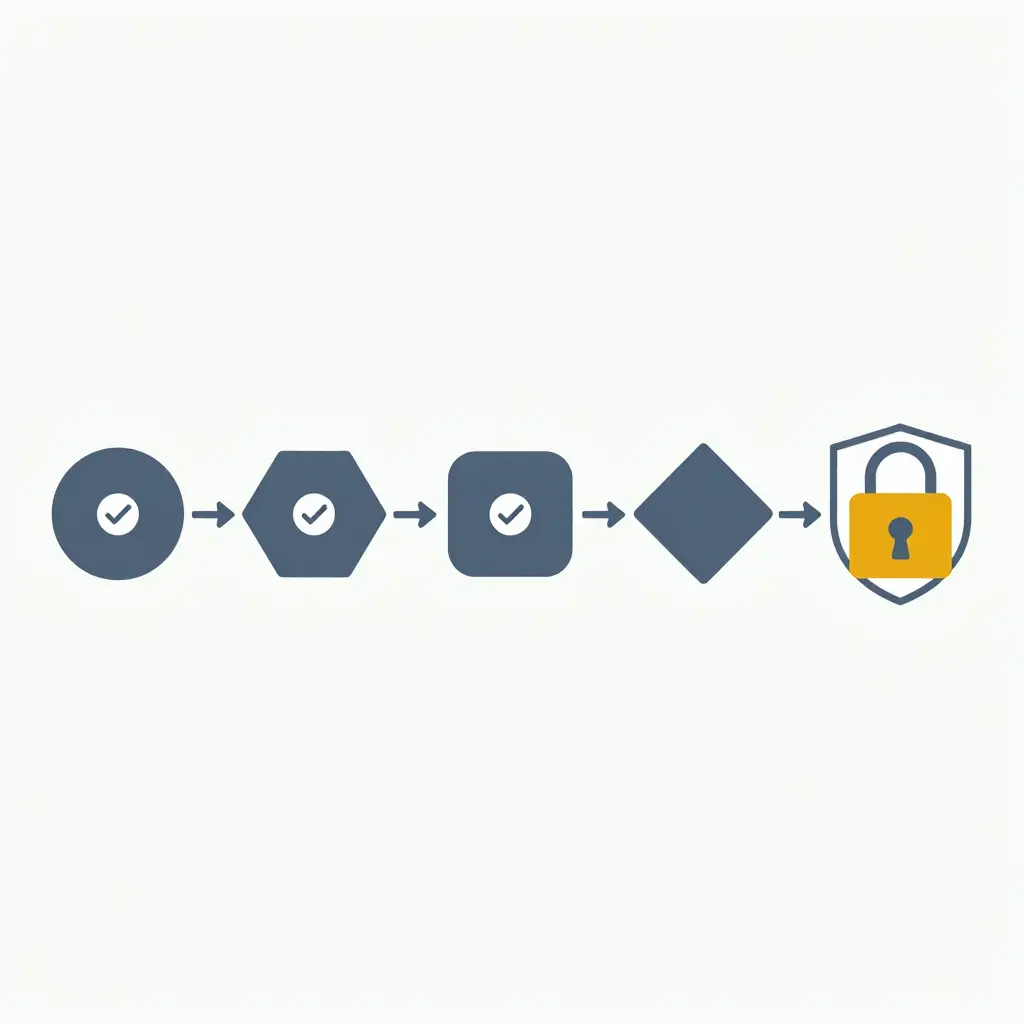
The freeze gate flow, left to right, ending in a locked configuration.
Pump Module Compatibility Checkpoints Before Design Freeze
Before a custom fire apparatus moves past design freeze, the pump module has to be reconciled against the chassis and body on paper, not on the shop floor. The spec writer, project engineer, and pump module builder each sign off on the checkpoints below, and drawing revisions get recorded against a controlled release number. Confirm that the selected module’s pump capacity rating matches the intended fire flow demand before clearing these gates.
- Frame rail drill pattern verification – Confirm hole spacing, rail height, and mounting bracket locations match the pump module sub-frame without field drilling.
- Driveshaft angle and PTO output alignment – Validate U-joint working angles, shaft length, and PTO output spline alignment within the manufacturer’s allowable tolerance.
- Pump-to-tank plumbing diameter confirmation – Verify intake, discharge, and relief line diameters against the rated flow so no undersized runs throttle performance.
- Intake and discharge manifold placement – Check valve clearances, operator reach, and panel access against the body layout and required NFPA positioning.
- Front and rear axle weight distribution – Recalculate corner weights, GVWR, and reserve capacity with the module and full water load installed.
- Accessory and control panel reach – Confirm pump panel, gauges, and controls fall within ergonomic reach from the standing position on grade.
- Corrosion protection at dissimilar metal joints – Specify isolation washers, gaskets, or coatings wherever steel, aluminum, and stainless interfaces meet.
- Coolant, wiring, and hose routing clearance – Verify harness lengths, cooling line paths, and chafe protection around moving or heat-affected components.
- Serviceability and component removal envelope – Confirm the module can be accessed for impeller, seal, and valve service without removing the body.
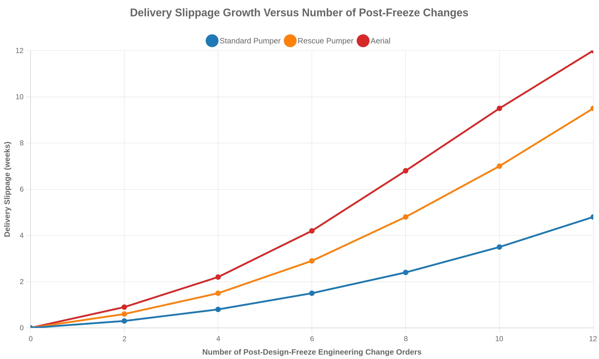
The chart’s two parallel upward slopes show schedule risk scaling with change volume, compounding rather than rising linearly. Every post-freeze engineering change order forces re-sequencing, re-procurement, and re-certification, and each one adds lead time. Aerial apparatus, with tighter axle and pump module tolerances, is estimated to absorb roughly 2.5 times the slippage of a standard pumper per change, which makes freeze discipline a procurement priority. Review how customization and lead time interact before contracting.
Axle Rating Constraints and Weight Distribution Realities
The axle rating is the load a given axle – with its springs, brakes, tires, and mounting hardware – is engineered to carry safely, and it is rarely as generous as the component list suggests. On custom fire apparatus, every pound added above the frame migrates between the front and rear axles, so pump module mass, water and foam tank loads, and body additions belong in a single shifting load case rather than a set of isolated line items.
A mid-ship pump module and a full water tank sit close to the rear axle, but plumbing, foam cells, and compartment shelving push weight forward or aft depending on layout. Add a generator, ladder rack, or hydraulic rescue tool cache, and the rig can approach its gross vehicle weight rating (GVWR) while one axle – frequently the front – already sits at its legal limit. Overload an axle and you invite cracked springs, brake fade, tire failure, and lost steering authority; exceed GVWR and bridge-law exposure and road-load restrictions grow with it. Bridge formulas penalize short wheelbases, so a legally loaded rig can still run over posted limits – compare this with how fire trucks interact with bridge loads.
Confirm the axle rating at the design freeze, not at final inspection. Once weights are locked, check wheelbase and rear-axle steering geometry together – see tiller and rear-axle steering selection. Move a tank or a shelving bank before the freeze; after it, changes mean re-engineering, added cost, and delivery slippage.
Illustrative Axle Rating Budget for a Custom Pumper
A design freeze is only as credible as the weight math behind it. Before locking a custom pumper configuration, the engineering team builds a load-and-balance budget that assigns each major component to the front or rear axle. The table below is an illustrative single-rear-axle custom pumper carrying a 1,000-gallon water tank, a 30-gallon foam tank, and a five-person crew. Treat every figure as a clearly labeled planning estimate for discussion, not verified product data from any specific build.
| Load Component | Estimated Weight (lb) | Front Axle Share (lb) | Rear Axle Share (lb) |
|---|---|---|---|
| Chassis and cab (est.) | 16,500 | 9,800 | 6,700 |
| Pump module and drive (est.) | 3,200 | 1,400 | 1,800 |
| Water tank, 1,000 gal including tank (est.) | 9,800 | 1,500 | 8,300 |
| Foam tank, 30 gal including tank (est.) | 400 | 80 | 320 |
| Hose and equipment (est.) | 2,600 | 700 | 1,900 |
| Body and compartments (est.) | 5,400 | 1,200 | 4,200 |
| Crew, 5 personnel at 220 lb (est.) | 1,100 | 900 | 200 |
| Component subtotal (est.) | 39,000 | 15,580 | 23,420 |
| Front axle rating (assumed) | – | 20,000 | – |
| Rear axle rating (assumed) | – | – | 31,000 |
| Remaining margin (est.) | – | 4,420 | 7,580 |
Reading the Budget
The subtotals put roughly 15,580 lb on the front axle against a 20,000 lb rating, and 23,420 lb on the rear axle against a 31,000 lb rating, leaving illustrative margins of about 4,420 lb and 7,580 lb. Water and body mass dominate the rear axle; cab, pump, and crew weight drive the front. Move one component – a heavier pump, a larger tank, a loaded compartment – and the balance shifts quickly. Confirm final figures on a certified weight ticket before the design freeze is signed; this is a companion step to budgeting a custom fire truck build.
Delivery Slippage: Root Causes and Contractual Controls
Delivery slippage in custom fire apparatus builds rarely comes from a single failure; it compounds through a few predictable chokepoints. The most common trigger is the post-freeze change order. Once the design freeze locks the pump module envelope, axle rating, and body layout, a late request for a larger water tank, extra compartments, or a revised pump panel reopens engineering, restarts CAD approvals, and resets the production slot. A revision can add weeks, and the delay cascades because the next truck in line waits.
Component lead times are the second driver. As general industry observations, custom chassis and cab builds commonly run 12-18 months, rear and specialty axles 24-40 weeks, fire pump modules 20-36 weeks, and aerial devices 30-52 weeks.
| Component | Typical industry lead time |
|---|---|
| Custom chassis and cab | 12-18 months |
| Rear and specialty axles | 24-40 weeks |
| Fire pump modules | 20-36 weeks |
| Aerial devices and ladders | 30-52 weeks |
| Foam proportioning systems | 16-30 weeks |
When an OEM discontinues a chassis or pump, builders substitute axles or pump modules, which forces re-validation of weight distribution and performance and adds another round of delivery slippage. Third-party inspections and pump certification tests slip on their own schedule, independent of production.
Contract clauses can contain some of it. Liquidated damages put a price on late delivery, milestone-based payments tie money to verified progress, and freeze-date clauses penalize post-freeze changes. For budgeting context, see budgeting a new fire truck and how much a new fire truck costs by chassis class and pump rating.
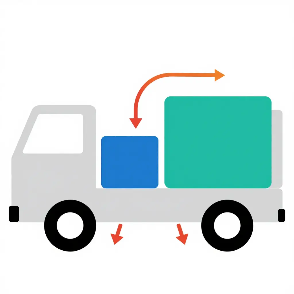
Figure: 2D axle load distribution schematic for a custom fire apparatus.
The diagram above isolates the single most consequential variable in any custom build: how component placement redistributes vertical load between the front and rear axles. The body rests on two contact points, front and rear, and each heavy subsystem is a mass block whose position along the chassis sets its moment arm to either axle.
Three things to read off it:
- The pump module block. Mounted mid-ship, it sits close to the chassis centerline. The lever arm to the front axle is longer than to the rear, so a mid-mounted module still sends a meaningful share of its weight rearward, especially once plumbing and the full pump enclosure are counted.
- The tank block. Placed toward the rear, the water tank is the dominant aft mass. Full, it drives the rear axle toward its gross axle weight rating (GAWR) far faster than most committees anticipate at the specification stage.
- The transfer arrows. The curved arrows show how shifting either block fore or aft changes the load split. Move the tank forward to relieve the rear axle and you load the front; move it back and you protect the front axle at the expense of the rear.
For a design freeze, the point is that axle rating is not a fixed input; it is an output of placement decisions. Once pump module geometry, tank length, and hosebed layout are locked, the axle split locks with them – which is why axle rating and component placement should be validated before the freeze. Confirm the split early and you avoid the mid-build redesign that so often cascades into delivery slippage.