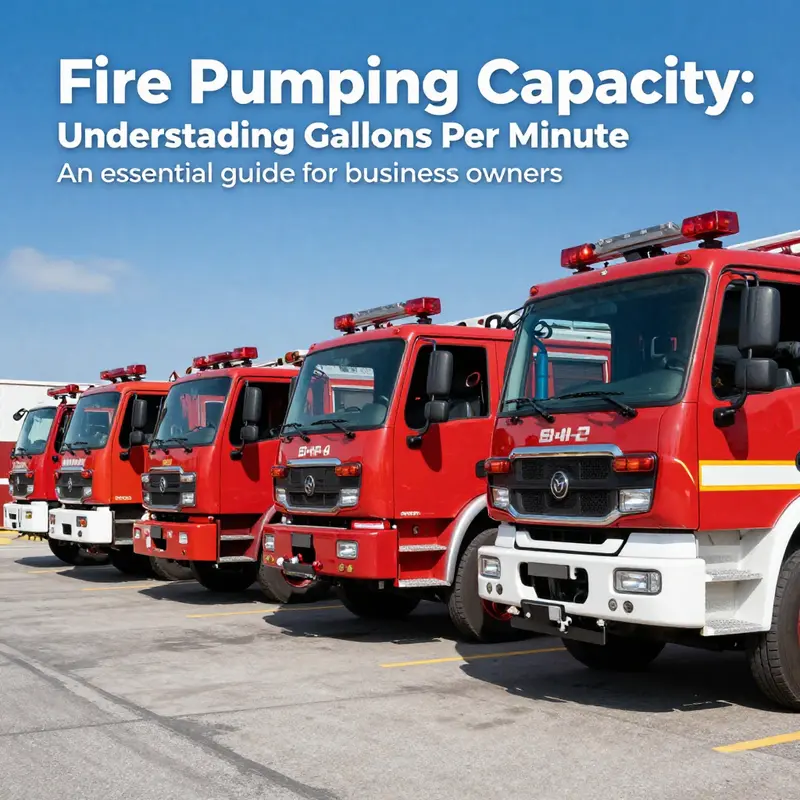
Mobile command vehicles fail in ways that repeat across incidents, and command vehicle generator and uplink faults account for a disproportionate share of on-scene outages. A generator that trips, a mast that sags, a call handover that drops mid-incident: each one costs the command post situational awareness while the incident is still running. The faults also travel. Power, structural, and control paths share hardware, so a failure in one domain reaches the others.
Three interdependent failure domains decide whether an incident command post stays on air:
- Sizing margin – the gap between a generator’s continuous rated output and the true steady-state plus transient load of the vehicle’s systems, worked out in kilowatts rather than assumed.
- Mast load – the combined static and wind-induced moment applied to a pneumatic or electric mast, its support or guy structure, and the roof or chassis mounting points that carry it.
- Call handover – the process by which an active radio or cellular/satellite session transfers between cells, satellites, or backhaul paths without dropping the call or corrupting data integrity.
The three domains feed each other. A larger electrical load raises heat and duty cycle; a taller or heavier mast assembly increases effective wind area and generator demand; a failed handover triggers radio retries that spike instantaneous power draw. Fleet planners evaluating communications layers also factor in radio interoperability across mutual-aid agencies when they specify this interconnect. The sections below take each subsystem in turn, quantify the fault modes that dominate it, and set out the specifications integrators and fleet engineers need to size, build, and run these vehicles.
Generator Sizing Margin for Command Vehicles
The generator keeps radios, server racks, and satellite uplinks alive during an incident. Specifying it by summing nameplate loads is the quickest way to earn field generator faults. Start instead with the sizing margin: the calculated headroom between expected demand and installed capacity.
Prime vs. standby ratings
- Prime rating: built for continuous duty, typically tolerating about 10% overload for one hour in every twelve.
- Standby rating: designed for emergency backup with no sustained overload capability.
A command vehicle that runs a 12-hour operational shift on a standby-rated set is outside its design envelope. The rating has to match the mission profile, not the price sheet.
Continuous vs. transient load
Continuous loads – comms racks, interior lighting, HVAC steady-state – define the running baseline. Transient loads behave differently: compressor starts, hydraulic mast elevation, and antenna drive motors pull several times their running current for a few cycles. The generator has to satisfy both, and the transient is usually what trips it.
Why undersizing causes voltage sag and frequency drift
When the sizing margin is too thin, voltage sag and frequency drift follow. Telecom racks brown out and reboot, uplink modems drop carrier sync, and call handover breaks mid-incident, a cascade that can leave a command post without working comms for minutes.
Diversity, inrush, and the recommended margin band
- Load diversity factor: not every load runs simultaneously; apply a realistic demand factor rather than a raw sum.
- Inrush current: HVAC compressors can draw 5-6x rated current, and antenna drives spike hard on start.
| Load element | Approx. factor | Sizing treatment |
|---|---|---|
| Diversified continuous | 0.7-0.9 | Baseline running load |
| HVAC inrush | 5-6x running | Verify transient capability |
| Antenna/mast drives | 3-5x running | Verify transient capability |
Recommended sizing margin: roughly 20-40% above the transient peak, with the diversified continuous load setting the floor. Load-budgeting discipline on the electrical side mirrors pump sizing on the fire side – see how fire truck pump capacity is matched to real-world demand.
PTO gensets vs. dedicated gensets
A chassis-mounted power take-off (PTO) generator leverages the truck engine and saves bay space, but its output is tied to engine RPM, so frequency stability depends on idle control. A dedicated genset decouples power from the driveline and delivers cleaner frequency for sensitive telecom equipment. Neither substitutes for an honest sizing margin.
Generator Sizing Margin by Mission Profile
Before you fix the diesel or turbine rating on a command vehicle, benchmark it against measured continuous demand and the transient peak created by mast raises, HVAC inrush, and uplink amplifier keying, then add a margin on top. The same logic applies to confirming fire pump capacity ratings: rate the component to the real duty cycle, not the marketing spec sheet.
| Mission Profile | Continuous Load (kW) | Transient Peak (kW) | Recommended Rated Output (kW) | Applied Margin over Transient Peak (%) |
|---|---|---|---|---|
| Light Command Post | 8 | 18 | 25 | 39 |
| Full Comms Shelter | 22 | 48 | 60 | 25 |
| Multi-Agency Incident Command | 38 | 82 | 100 | 22 |
| Extended Field Operations | 55 | 120 | 150 | 25 |
The applied margin is the headroom between the recommended rated output and the transient peak, expressed as a percentage of that peak. The rated output is then rounded up to the next standard size, which is why the Light Command Post row sits near the top of the band and the Extended Field Operations row lands above its nominal target. A larger margin absorbs cold-start derates and future load growth. Push a profile below its band and you get nuisance breaker trips, voltage sag during mast raises, and dropped uplink channels while the mast is up.
Mast Load: Static vs. Dynamic Wind, Overturning Moment, and Ground Reaction
A deployed telescoping mast behaves as a cantilever, and mast load governs the structural design of the whole command vehicle. Wind load is dynamic pressure times projected area times a gust factor: q = 0.613·v² (Pa) for a 3-second gust, multiplied by the projected area A of the mast and head. Static wind loading treats q as steady. Dynamic loading adds a gust effect factor G_d of roughly 1.6-2.0 for slender masts and can excite vortex shedding at the resonant frequency, so dynamic wind load can reach twice the static figure at the same nominal wind speed.
Overturning Moment as a Function of Height and Payload
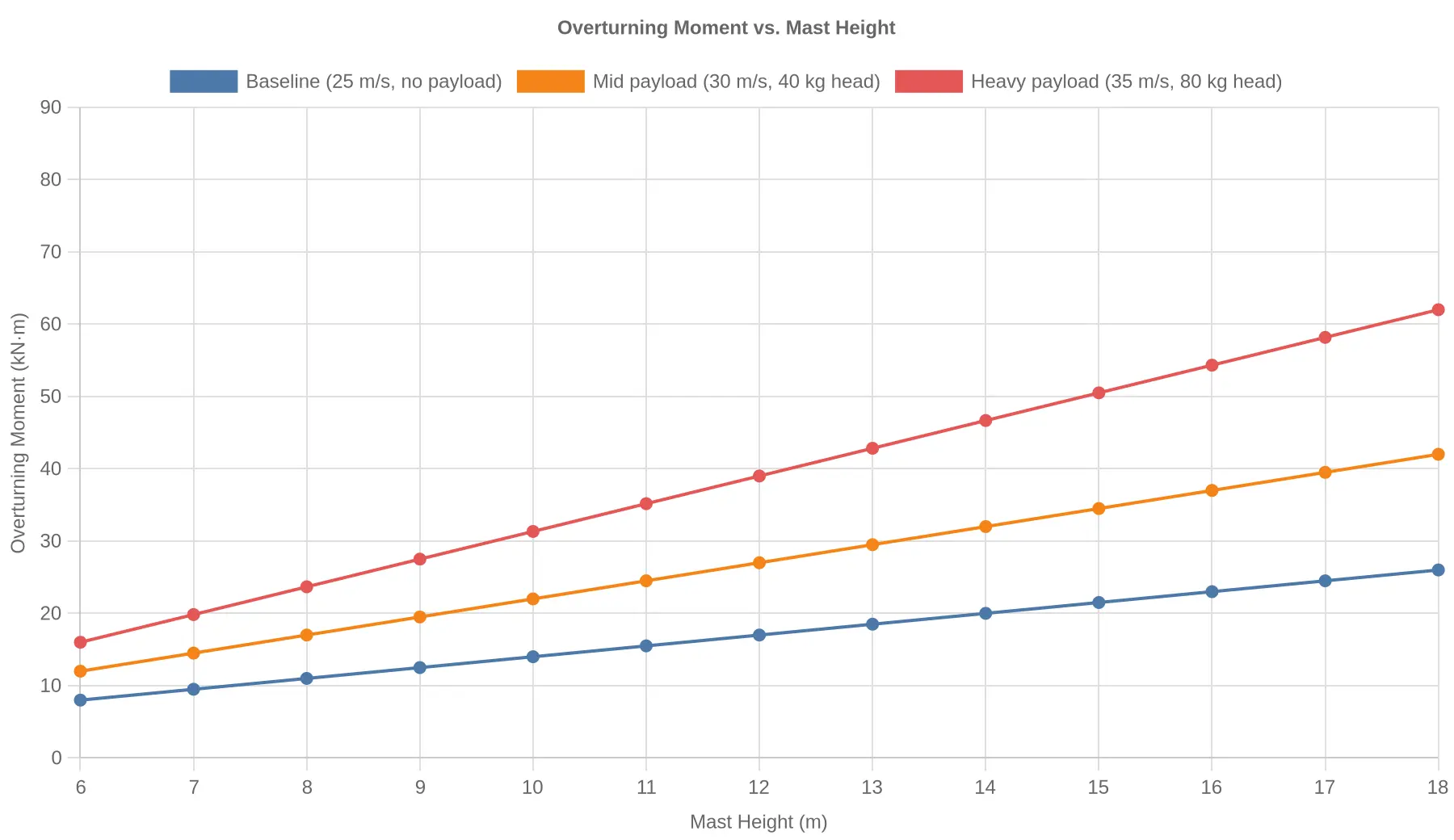
The overturning moment adds each load element times its height above the ground pivot: M = Σ(Fi × hi). It grows linearly with mast height and with the projected area of the head, so an added antenna array or PTZ camera shifts the load case sharply. The chart below shows how the moment grows with height across three payload classes.
Outrigger Reaction and Ground Bearing Pressure
At full extension the outriggers or leveling jacks resist the moment: R = M / b + W/4, where b is the outrigger spread and W the total vehicle weight. Ground bearing pressure is the jack reaction divided by the pad area, and it has to stay below the allowable soil capacity (commonly 100-300 kPa). The mechanics match aerial apparatus stabilizer design, and the failure modes are the same whether the load is a ladder tip or a mast head, as detailed in this guide to aerial ladder truck outrigger faults, ground bearing pressure, and slope checks.
| Mast Height (m) | Overturning Moment (kN·m) | Outrigger Reaction R (kN) | Ground Bearing Pressure (kPa) |
|---|---|---|---|
| 10 | 14 | 24.7 | 98.7 |
| 14 | 20 | 26.7 | 106.7 |
| 18 | 26 | 28.7 | 114.7 |
(b = 3.0 m, W = 80 kN, pad area 0.25 m²)
Tip Deflection and Uplink Faults
Antenna and camera payload at the mast tip adds mass and area at the point of maximum lever arm. Tip deflection follows δ ≈ F·L³ / (3·E·I), so it grows with the cube of the exposed length and in proportion to the tip load. At 18 m, a 0.5° elastic deflection displaces the head roughly 157 mm. For a Ku-band aperture that translates directly into pointing error and gain loss; once deflection exceeds the monopulse tracking threshold, the terminal loses lock and the modem reports an uplink fault. Vertical reach and structural stiffness therefore matter as much as raw height, the same trade-off that sets the geometry that defines how far an aerial ladder can reach.
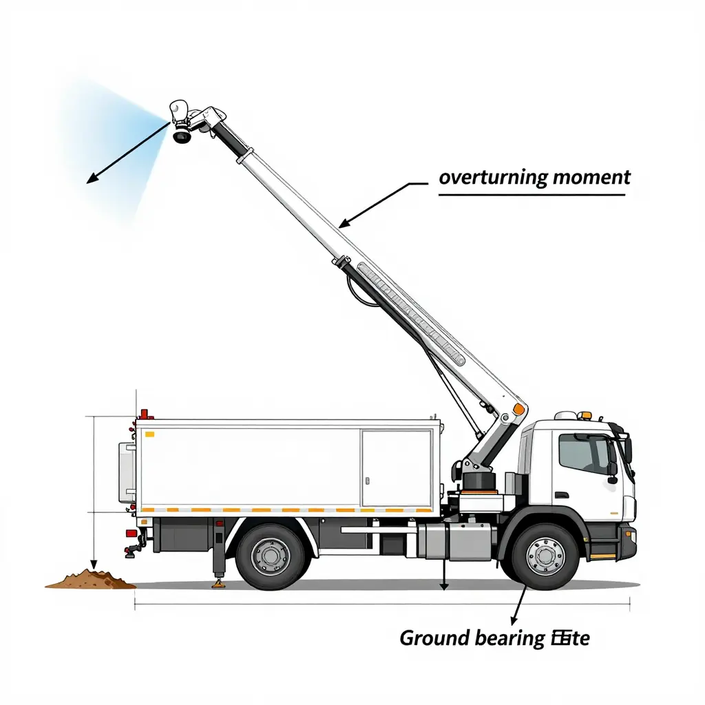
Exceeding the rated mast load fails gradually rather than cleanly. Pointing accuracy degrades first; under gust loading the uplink faults turn intermittent, then persistent, often during the handover the crew most needs.
Mast load vector diagram
Four forces act on a raised command-vehicle mast at once, and together they set its structural margin:
- Wind load – applied horizontally along the exposed height of the mast, scaling with the square of wind speed and the effective projected area.
- Payload weight – applied vertically at the mast tip, where the antenna head and uplink assembly sit furthest from the pivot.
- Overturning moment – the rotational resultant about the base, produced by wind load times its lever arm plus payload weight times horizontal offset.
- Outrigger reaction – the counteracting upward force at ground level that resists the overturning moment and keeps the base within its bearing and slope tolerance.
Each arrow below shows the direction of one force. The schematic carries no text so the vector relationships read cleanly at technical review.
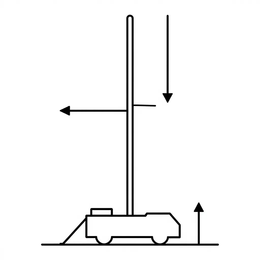
Outrigger reaction is the term crews underestimate most. Skip the ground bearing or slope check and the margin between calculated reaction and soil capacity can vanish on a soft apron. For how outrigger faults, ground bearing pressure, and slope limits interact on heavy apparatus, see this guide to aerial ladder truck outrigger faults, ground bearing pressure, and slope checks.
Call Handover in Satellite and Cellular Uplink Systems
A command vehicle usually rides two bearer domains at once: one or more satellite spot beams on the space segment and terrestrial LTE/5G cells on the ground segment. A call handover transfers an active voice or data session from one serving node to the next without dropping the bearer. Satellite handover triggers fire when the elevation angle to the current beam falls toward the mask, when carrier-to-noise (C/N0) crosses a hysteresis threshold, or when the vehicle crosses a beam-edge contour. Terrestrial handovers follow RSRP/RSRQ and A3/A5 measurement events gated by time-to-trigger dwell timers. Both depend on the link budget: EIRP, G/T, path loss, and rain fade determine whether a candidate link can hold the session before the serving link releases.
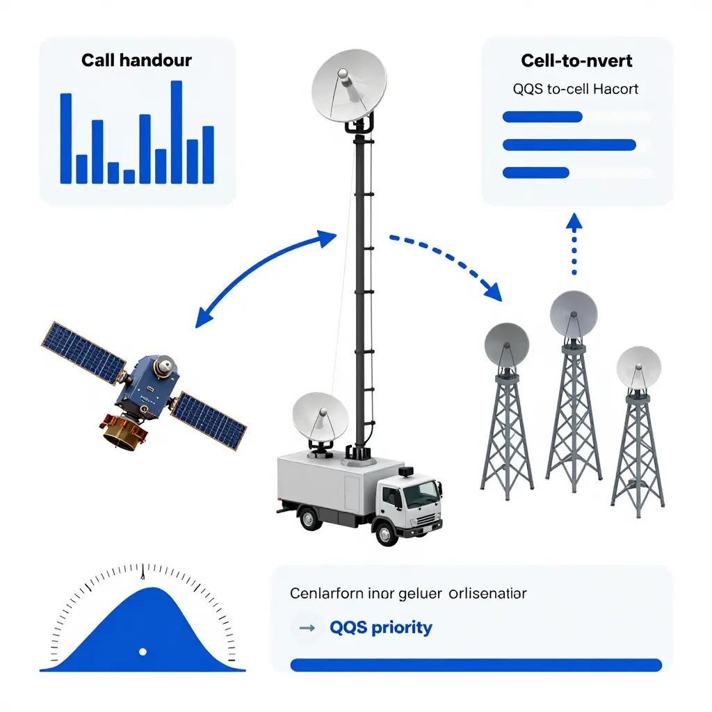
The failure is transient, not binary. During handover the forwarding path breaks briefly, producing packet-loss bursts and latency spikes that jitter RTP voice streams and stall control traffic. Mast movement compounds this: sway and slew push the antenna boresight off axis and erode pointing margin, while frequency or voltage drift from the generator during transfer can brown out modems and force re-registration mid-sequence, a common source of uplink faults.
Robust designs fail over between primary and backup bearers (satellite-to-cellular or dual-SIM) under QoS-aware routing. Voice is marked EF and data AF, so a degraded bearer sheds bulk data before voice. Uplink reliability controls remote assets the same way, as in firefighting robot deployment on airport aprons, where a stalled bearer means a stalled machine.
Root Causes of Command Vehicle Uplink Faults
Lose the uplink during a prolonged incident and video backhaul, CAD synchronization, and dispatch coordination all go with it. The satellite or the modem itself is rarely the cause. Uplink outages usually trace to a few recurring domains upstream of the RF link, in the power, mechanical, and network layers.
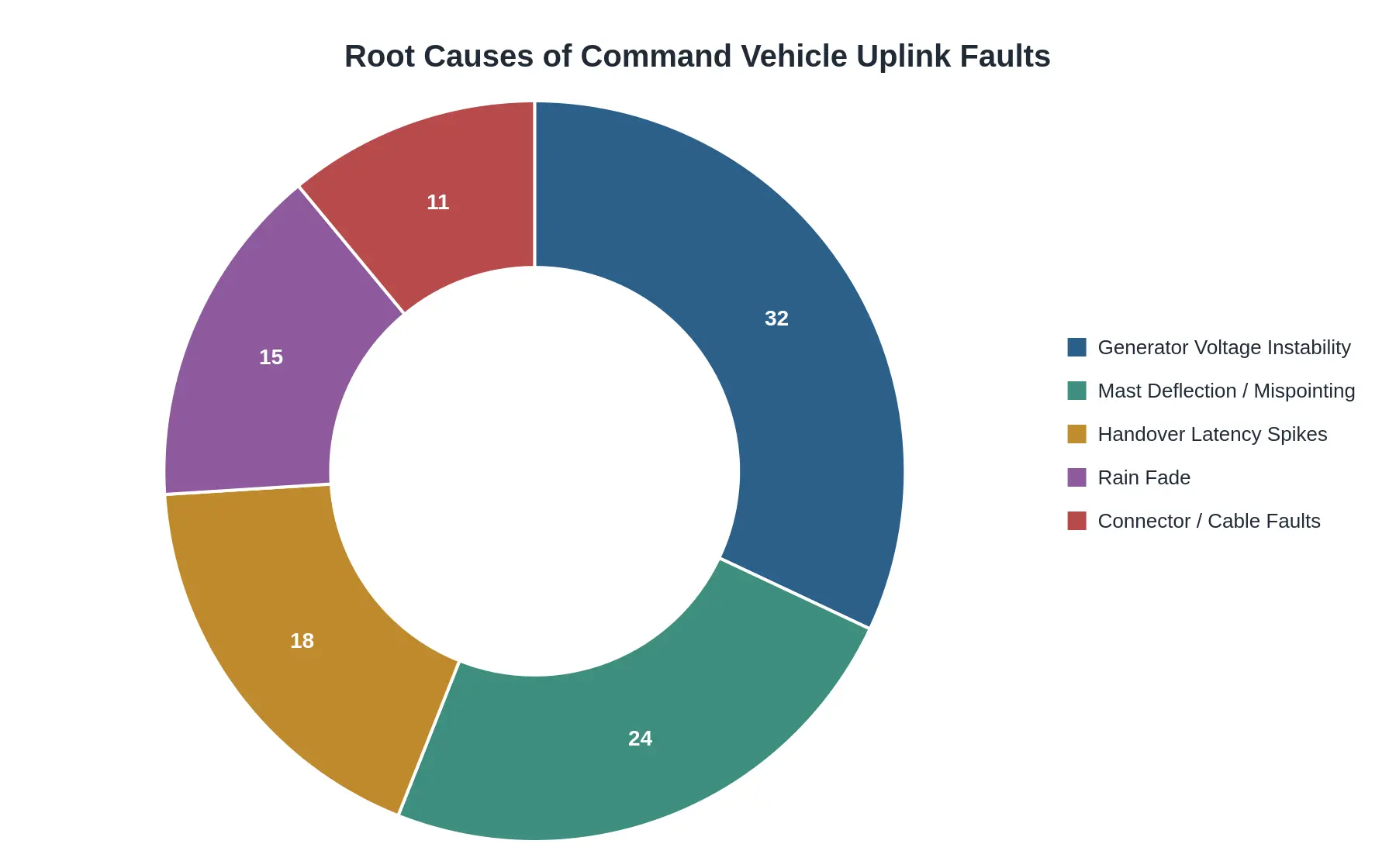
The doughnut chart below groups fault events into five root-cause categories, drawn from field-service records and telemetry for mobile command platforms. Generator voltage instability leads at roughly a third of all events, which fits the tight margins these vehicles run: a genset that is undersized for mast actuators, HVAC, and comms racks at once will sag or spike under load transients. Mast deflection and mispointing follow at nearly a quarter, often because ground bearing and slope checks get skipped during rapid deployment.
Handover latency spikes and rain fade together account for about a third of incidents, reflecting the mix of terrestrial and satellite paths these units rely on. Connector and cable faults are the smallest share but cause a disproportionate number of intermittent, hard-to-diagnose dropouts.
Reading the Distribution
Whether you are specifying a new command platform or troubleshooting an existing one, this distribution should set your priorities. The top two segments – generator voltage instability and mast deflection – are engineering and specification decisions made long before the first call, not field faults you can patch on scene. The largest reliability gains therefore come from sizing the generator with a real transient margin and specifying mast and stabilization hardware that holds pointing accuracy across the tilt range, not from stocking spare modems.
Reading the architecture
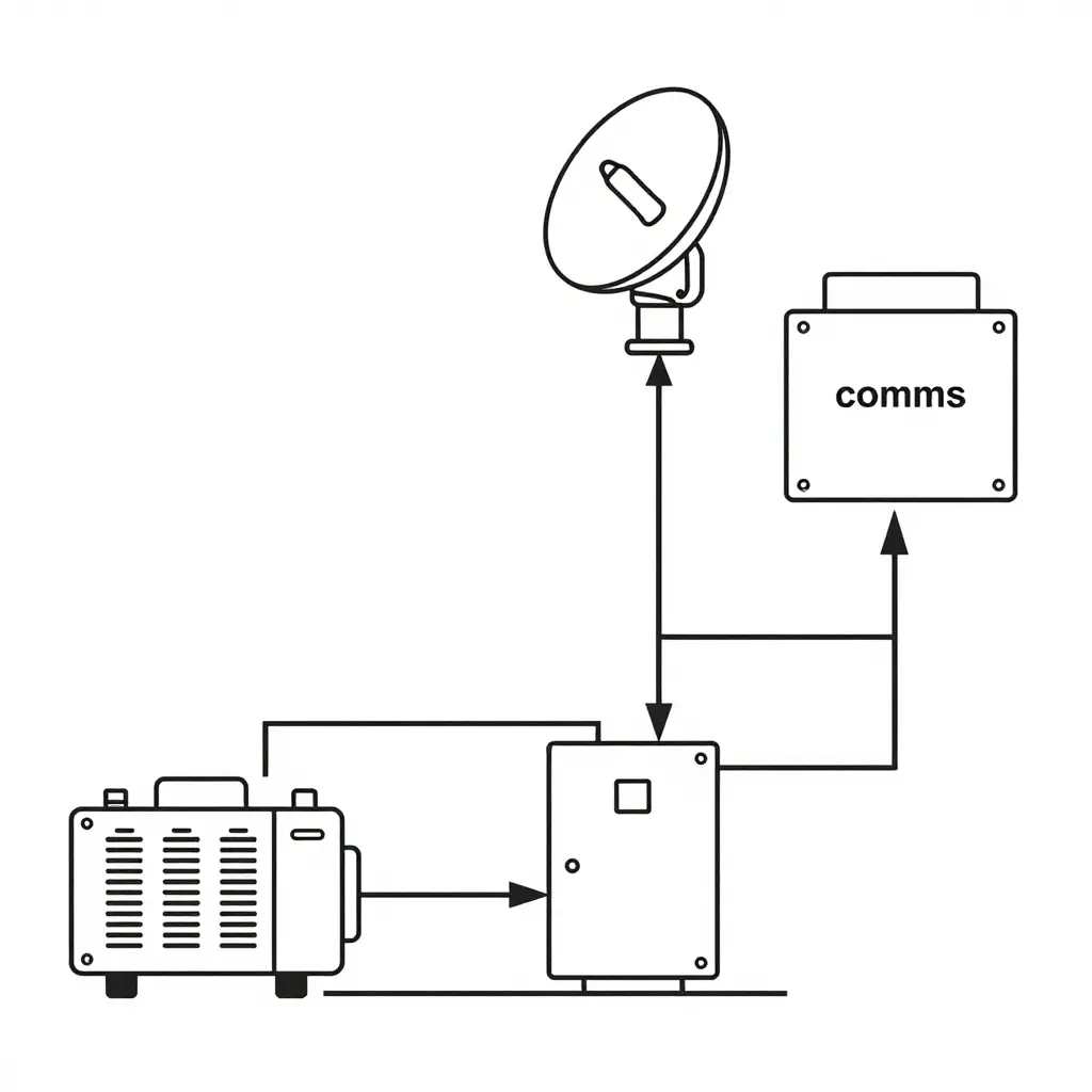
The diagram traces two coupled domains in one command vehicle platform. In the power domain, two independent sources – the onboard generator/genset and shore power – converge on the distribution panel, which handles load scheduling, breaker protection, and phase management before any current reaches the electronics.
A directional feed runs from the panel to the comms rack, where power meets payload. The rack conditions and distributes DC to radios, modems, and mast actuators, and the same rack hosts the signal chain that drives the mast-mounted antenna and, ultimately, the satellite and cellular uplink.
The split matters when you diagnose faults. A thin genset margin or a shore-power phase mismatch upstream degrades the rack and shows up downstream as dropped call handover or mast load-induced brownouts. Treat the two domains as one serial chain: instability anywhere propagates end to end. For comparable analysis of load-path and ground-bearing stability, see this analysis of outrigger load and ground-bearing checks.
Closing Procurement and Specification Guidance
Bind the power, mast, and handover domains into a single specification package, and the vehicle is more likely to survive a real incident. Procurement and technical staff should write these findings into tender clauses as mandatory requirements, not advisory notes, so every subsystem carries verifiable headroom rather than optimistic nameplate figures.
Recommended minimum sizing margin bands
| Subsystem | Recommended minimum sizing margin | Tender verification requirement |
|---|---|---|
| Generator / prime power | 25-30% headroom above continuous critical load | Load-bank test at rated load with 10% step response recovered in under 15 seconds |
| Mast / structural load | 1.5 times safety factor on rated payload, including ice and wind | Static proof-load test plus wind-load calculation to rated gust speed |
| Uplink / RF chain | 3 dB combined radio and rain-fade margin | Documented worst-case link budget at minimum elevation angle |
Mast load verification requirements
Require mast load verification as a signed structural calculation, not a catalogue claim. Bidders should demonstrate headroom for the full antenna complement plus cabling and ice accumulation, and quote the derated payload at maximum extension.
Handover resilience criteria
Tender documents should require uninterruptible power transfer in under 500 ms, dual-path uplink failover, and a documented pre-transfer checklist that isolates the most common command vehicle generator and uplink faults. Match those clauses to proven customization lead times so the specified margin is not stripped away later during value engineering.
Anchor the specification language in established practice, as set out in CIMC Tianda’s T-Line fire apparatus guidance, where integral sizing margin is written into the base design rather than added as an option.
Adequate sizing margin across power, mast, and uplink keeps a command vehicle in contact through generator step loads, full mast extension, and satellite handover, without dropped calls or degraded incident command.