Firefighting Robots on the Airport Apron: The Next ARFF Frontier
A fuel spill beneath a parked wide-body can turn a routine turnaround into an incident in seconds. The airport apron leaves little room to work with – aircraft, jet bridges, tugs, and ground crews share the same concrete – so every meter of response distance matters and every extra minute of exposure raises the risk. That is why a firefighting robot is moving out of the laboratory and onto the apron.
Today’s crash tenders are crewed, and that is the constraint a robot removes. An autonomous or remote-operated unit can drive into the spill zone, put a monitor on a hot tire or engine nacelle, and knock down fire with nobody inside the hazard envelope. As airports harden their ARFF vehicle manufacturers and safety strategies, the robotic option reads less like a novelty and more like the next step in a doctrine that already exists.
Bolting a nozzle onto a chassis is the easy part. Three constraints decide whether the concept works on a real apron:
- Heat shielding – protecting sensors, wiring, and batteries when radiant flux from a jet-fuel fire spikes.
- Battery endurance – sustaining enough usable runtime to reach, fight, and retreat from a fire on a single charge.
- Remote link loss – guaranteeing safe behavior when the wireless command channel degrades, jams, or drops entirely.
The sections below take each constraint in turn, with the numbers, failure modes, and operating practices that matter to aerospace engineers, airport operators, and firefighting-technology developers.
Heat Shielding: The First Constraint on the Apron
When a fuel-fed fire is burning, a firefighting robot usually rolls toward it while the rest of the response team holds back. The machine becomes the exposure point, and its heat shielding sets how close it can get and how long it can stay.
How the apron loads the chassis
The threat that does most of the damage is radiant heat: infrared energy pouring off a pool fire or a burning wing, raising surface temperatures without ever touching the machine.
Jet-A burns hot and burns long, and a ruptured wing tank can keep feeding a fire that pushes energy into everything in line of sight.
Time is the multiplier. Even a modest heat flux turns dangerous once a machine sits in it for minutes rather than seconds. Crewed vehicles sidestep the problem by working from a standoff distance, which is what top ARFF fire trucks are built to do; a robot that closes the gap takes on the full load.
Where the stress lands
- Chassis: steel and aluminum lose stiffness as they soak up heat, and seams and seals distort and open gaps.
- Sensors: thermal cameras, LiDAR, and IR optics drift or fail long before the frame does, and calibration is lost silently.
- Electronics: motor controllers, battery packs, and radios have the tightest limits and the least tolerance for surprises.
Passive protection
Passive shielding needs no power, so it cannot fail on you; all it does is buy time.
- Reflective skins bounce radiant energy away. Polished panels with low emissivity reflect heat instead of absorbing it – the same property that keeps fire trucks visibly distinct on the apron.
- Insulating blankets slow conduction into the structure.
- Ablative layers sacrifice themselves, charring and flaking away to carry heat off the robot.
Active protection
Active systems spend energy to stay ahead of the heat. Coolant circulates through the hottest zones around batteries and controllers, and fans push air across surfaces and out of electronics bays to break up trapped heat. The trade-off: active protection is only as reliable as its pumps and its power supply.
The weight trade-off
Every layer of shielding adds mass, and mass comes out of payload, acceleration, and battery endurance – the other two constraints in play. Designers therefore trade protection depth against how close and how long the robot actually has to work, instead of armoring for the worst case everywhere.
Get that balance right, and shielding stops being the weak point. It becomes the reason a robot can enter heat no crew would be sent into.
Heat Shielding Approaches for Apron Firefighting Robots
No single thermal protection strategy wins on every apron. Reflective barriers, insulating blankets, intumescent coatings, active cooling, and ablative layers trade weight, endurance, and cost against one another. The table compares their engineering characteristics before you specify protection for a robot working near jet-fuel fires and hot metal.
| Approach | Primary Mechanism | Typical Material | Key Strength | Main Limitation |
|---|---|---|---|---|
| Reflective foil shielding | Reflects radiant heat away from exposed surfaces | Aluminized fiberglass or stainless steel foil | Lightweight, low cost, reflects most radiant heat before it penetrates | Poor against convective or contact heat; foil tarnishes and loses reflectivity |
| Aerogel insulation blankets | Traps heat through a nanoporous structure with very low thermal conductivity | Silica aerogel encapsulated in fiber batt | Highest thermal resistance per unit thickness and weight | Brittle and dust-prone, costly, and requires protective encapsulation |
| Intumescent coatings | Swells and chars when heated, forming an insulating carbon layer | Epoxy or silicate-based intumescent resin | Passive, activates only under fire, conforms to complex geometry | Single-use activation, limited protection duration, adds surface weight |
| Active liquid cooling | Circulates coolant to carry heat away from critical components | Water-glycol loop with heat exchangers and pumps | Sustained protection for long-duration exposure, actively controllable | Needs power, plumbing and coolant supply; higher complexity and weight |
| Sacrificial ablative layers | Material chars and vaporizes, absorbing heat as it is consumed | Cork, phenolic composites, ablative elastomers | Very high short-term heat absorption, mechanically simple | Consumed over time and must be replaced after each exposure |

How the Layers Work Together
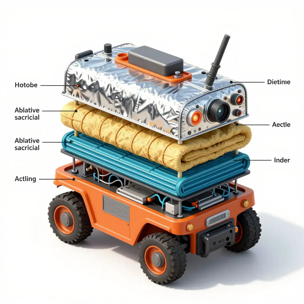
The diagram above is a cross-section of a critical electronics enclosure protected by a four-layer thermal stack. Each layer defeats a different form of heat transfer, and together they buy the internal core time as the robot approaches a burning aircraft.
- Outer reflective skin – A thin, low-emissivity surface that bounces radiant heat away before it can be absorbed. Radiant load usually arrives first and hardest on an apron fire, so reflectivity earns its keep at the outer boundary.
- Insulating blanket – A fibrous, low-conductivity wrap that slows conductive and convective heat creep through the structure, acting as the bulk thermal resistor.
- Thermal barrier layer – A dense phase-change or intumescent sheet that soaks up peak heat spikes, absorbing energy as temperatures briefly push past steady-state limits.
- Protected internal core – The electronics bay itself, held inside a design envelope where temperature stays within the operating range of the battery, radios, and control boards.
Read top to bottom, the stack follows one rule: reflect first, insulate next, absorb the spikes, keep the core cool. Teams already weighing how heat and payload shape platform design will recognize the same logic in the top ARFF truck manufacturers shaping airport safety.
Battery Endurance: The Energy Budget of an Apron Mission
An apron robot does not sip power in a straight line. Its battery endurance is set by a mission profile that swings between near-idle vigilance and full-throttle suppression, which makes it the second of the three constraints here, alongside heat shielding and link integrity. Think of it as a budget spent in bursts rather than a tank drained at a steady rate.
The chart below shows what each phase pulls from the pack.

Standby: the quiet sip
Between alerts, the robot holds position, runs its sensors, keeps the datalink alive, and manages the temperature of its electronics. Draw is low but never zero – a unit idling in direct apron sun spends energy on thermal management alone.
Transit: the rolling cost
Crossing the apron at speed loads the drive motors continuously. Wind, tire rolling resistance, and any onboard payload stack onto that draw. A long run to a remote stand can quietly take a fifth of the pack before a single liter of agent flows.
Suppression: the peak
This is where battery endurance evaporates fastest, because the monitor, pump, and proportioning system all compete for current at once. Delivering agent at rated pressure demands serious power, and the electrical load scales closely with pump delivery capacity, so a robot asked to run near its hydraulic ceiling will flatten a pack in minutes rather than hours. Operators who understand proportioning drift and refill timing also know that a struggling foam system forces longer discharge times, which drains the battery further.
Retreat: the recovery window
Pulling back to a safe staging point is lighter than suppression but heavier than standby, since the drive system is loaded while the electronics stay active. This is the phase where operators find out whether their earlier estimates were honest.
What moves the needle
- Payload. Every kilogram of agent, tools, or shielding has to be hauled out to the fire and back.
- Ambient heat. Elevated apron temperatures reduce usable lithium capacity and raise internal resistance, which shows up as voltage sag and earlier derating.
- Fixed charging vs. fast-swap. Fast-swap packs restore readiness in minutes and suit continuous coverage; fixed charging is simpler but leaves the robot out of service far longer.
On a hot apron, lithium cells hold less charge and deliver it less gracefully. Heat also accelerates aging, widens discharge variance, and can trip a protection cutoff in the middle of suppression, which is the worst possible moment for it. Pairing fast-swap logistics with conservative thermal limits is what keeps a fleet genuinely mission-capable.
Keeping an apron firefighting robot mission-ready comes down to treating endurance as an operating discipline rather than a spec-sheet number, so crews can stretch every charge and stay in the fight between callouts. Six habits do most of the work:
- Plan duty cycles around real incident profiles. Alternate short high-draw suppression bursts with low-power standby mode so the pack never depletes during the critical first minutes of a response.
- Manage pack thermals proactively. Apron surfaces and radiant heat push cell temperatures high, so route cooling airflow, monitor cell-level temperature, and pause fast charging when ambient heat threatens safe limits.
- Standardize fast-swap battery modules. Design tool-free, hot-swappable packs with uniform connectors so a drained module is exchanged in under a minute instead of waiting on a full recharge.
- Shed non-critical sensor loads. During suppression, drop thermal-imaging redundancy, telemetry pings, and comfort systems, protecting only mission-critical loads like the foam proportioning and refill cycle that keeps discharge effective.
- Monitor charge state continuously. Stream state-of-charge and state-of-health data to the command console, with alerts well before reserves fall below the safe return threshold.
- Route efficiently between hotspots. Pre-map the shortest, lowest-resistance paths across the apron so the robot spends energy fighting fire rather than driving empty tarmac.
Battery Endurance: How Duty Cycle Shapes the Mission Clock
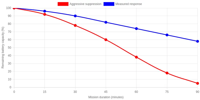
A robot cannot sprint and endure at the same time. On an apron machine, the biggest lever on endurance is not battery chemistry – it is how hard the operator drives the pump, the monitor, and the drive motors. The chart plots remaining capacity against mission duration for two realistic duty-cycle profiles.
Reading the two curves
Both profiles start fully charged at 100%, then diverge fast.
- Aggressive suppression – continuous monitor flow, repeated hard acceleration across the apron, cooling fans running flat out. The pack drops from 78% at 30 minutes to 38% at 60, and down to 5% by 90 – effectively no reserve left.
- Measured response – intermittent high-flow bursts, smoother acceleration, and staged cooling-fan demand. The same pack holds roughly half its capacity at 90 minutes, leaving real margin for secondary tasks or a controlled retreat.
At the 90-minute mark the two curves sit 45 percentage points apart, which is the difference between a driving style that lives at the redline and one that respects the energy budget.
The numbers behind the curves
| Mission duration (min) | Aggressive suppression (%) | Measured response (%) |
|---|---|---|
| 0 | 100 | 100 |
| 30 | 78 | 90 |
| 60 | 38 | 74 |
| 90 | 5 | 50 |
Why this matters on the apron
Apron geometry punishes waste. Wide-open concrete means long transit runs to a hot spot, and every hard launch draws a burst of current that a steady cruise would not. When a robot is coordinating with crewed assets, the battery curve becomes a scheduling tool rather than a gauge. Dispatch the aggressive profile only when the hazard demands it; run the measured profile otherwise and buy the team a longer working window.
The practical rule is to match duty cycle to hazard severity rather than to adrenaline. The robot that finishes its mission is worth more than the one that ran out of electrons chasing a fire it never needed to sprint toward.
Remote Link Loss: When the Operator’s Signal Disappears
An apron firefighting robot is only as effective as the link to its operator. When that link breaks – remote link loss – a heavy machine carrying a high-pressure water cannon and a load of foam concentrate must not become an uncontrolled hazard among fueled aircraft, crowded gates, and moving ground support equipment. No design prevents every dropout. What matters is that the robot behaves safely the instant one happens.
Why airport aprons punish radio links
The apron is one of the most hostile electromagnetic environments in aviation. Dozens of transmitters compete for the same spectrum at once: UHF radios, ADS-B, ground surveillance radar, Wi-Fi, and cellular traffic all crowd the airwaves.
Physical obstruction compounds the problem. A widebody fuselage parked between the robot and its controller can block line of sight entirely, and the layout shifts by the minute. Operations that cycle aircraft through stands, drive ramps, and fixed boarding infrastructure – the same apron drive versus fixed ramp boarding bridges trade-off planners already weigh – keep that geometry in constant flux.
Latency adds a third layer of risk. Even when packets arrive, a delayed command means the operator is steering a machine that has already moved, a dangerous mismatch near a wing tip or a fuel port.
Mitigation strategies that keep robots safe
| Risk factor | What goes wrong | Mitigation |
|---|---|---|
| RF interference | Control packets corrupted or lost | Frequency hopping, dual-band redundancy |
| Aircraft obstruction | Line-of-sight shadowed | Mesh relays, keep-alive beacons |
| Latency | Commands arrive after the robot has moved | Onboard autonomy, velocity limits |
| Total dropout | Operator has no control | Fail-safe stop, heartbeat timeout, auto-retreat |
Fail-safe autonomy is the first line of defense. Onboard perception lets the robot hold position, stop, or creep to a safe zone without waiting for instructions.
Redundant communication links provide a second path. Dual-band radio, cellular, and mesh relays fail over automatically, so losing one channel rarely means losing control – the same layering that keeps fire pump priming reliable under pressure.
Heartbeat protocols close the loop. The robot pings the operator continuously; if several heartbeats go unanswered, it drops into a degraded mode instead of continuing blindly.
Predetermined retreat behavior gives every mission a defined fallback. The robot navigates to a pre-mapped safe zone, shuts down its pump, and waits for a human to re-establish contact.
Redundant Communication Architecture: Preserving Control When the Link Drops
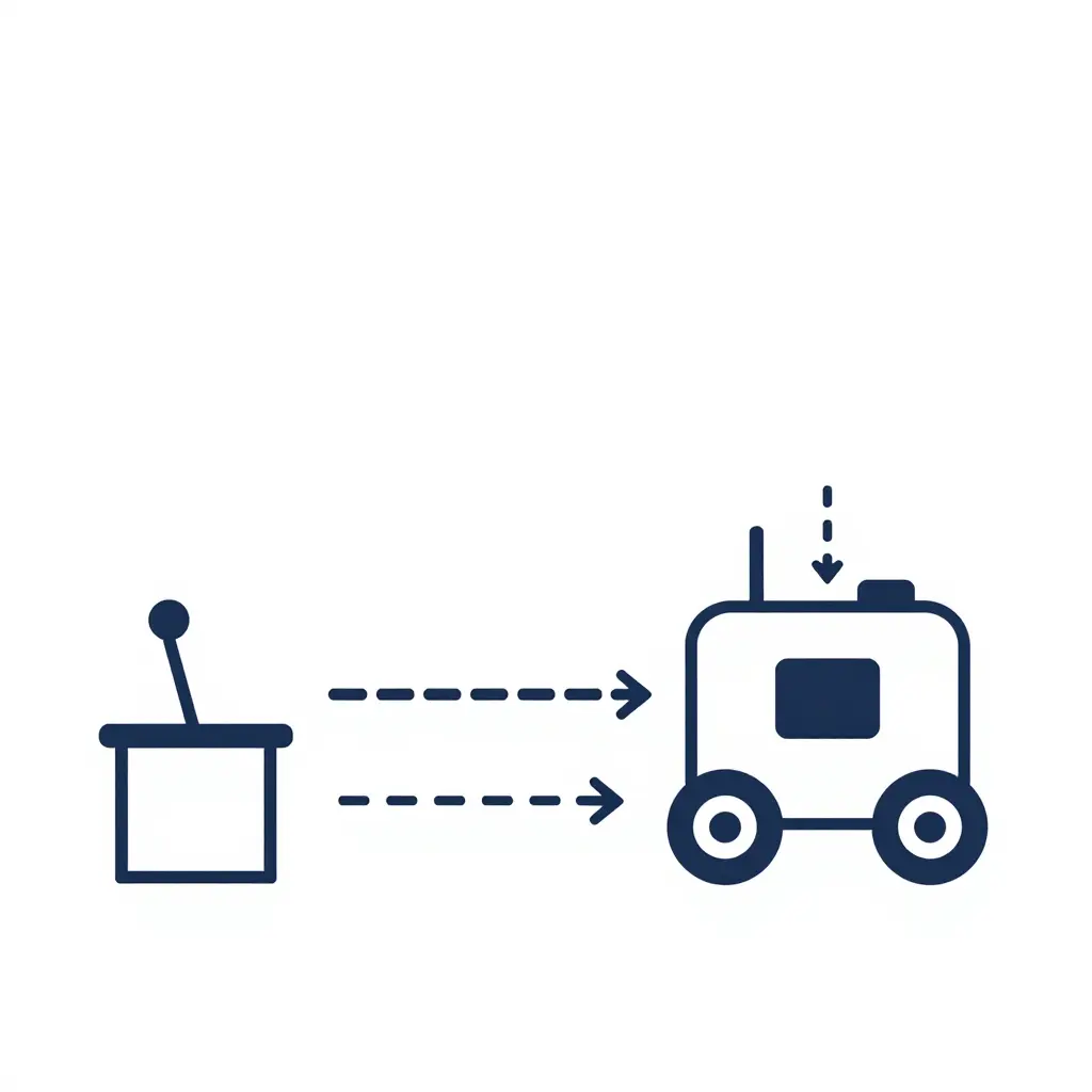
The schematic below maps the control chain for an apron firefighting robot: an operator control station, a primary radio link, a parallel backup link, and an onboard autonomous fail-safe module. The dotted arrows trace the failover logic – if the primary radio link drops, control hands off to the backup link and, failing that, to the onboard fail-safe module, so the unit keeps operating instead of freezing mid-apron.
For airport teams reviewing manufacturer claims around airport safety systems and ARFF equipment, this layered approach is the difference between a momentary telemetry gap and a stranded vehicle blocking a taxiway.
Frequently Asked Questions About Apron Firefighting Robots
What are the heat shielding limits for apron firefighting robots?
Most apron firefighting robots use layered ceramic and aerogel blankets rated for radiant heat fluxes around 20-30 kW/m², with short-duration tolerance near 1,000 °C. Sensors and cameras sit behind sacrificial shields that degrade gracefully. Beyond roughly 60 seconds inside the most intense fuel-fire zone, internal electronics need active cooling, which keeps positioning and standoff distance in play as design variables.
How long can the battery realistically last?
Expect two to four hours of continuous operation under realistic apron duty cycles, not the eight hours found on marketing sheets. Pumping foam at full pressure, running thermal cameras, and driving against wind all drain packs quickly. Many departments adopt hot-swappable battery modules or a tethered top-up option so a robot keeps working while its partner unit charges nearby.
What happens if the remote control link is lost?
When the command link drops, a well-designed robot enters a fail-safe state rather than freezing or driving blind. It halts movement, keeps foam flowing briefly if it is adjacent to a fire, and broadcasts its last known position to the control room. Automatic return-to-home routines and onboard obstacle sensors let it retreat safely until the operator re-establishes contact.
Can robots integrate with our existing ARFF trucks?
Robots complement ARFF trucks instead of replacing them. They share the same foam concentrates and can refill from truck-mounted tanks, while commanders feed them targeting data from the truck’s thermal imaging and turret controls. Choosing units with standard coupling sizes and open communication protocols keeps the fleet interoperable. Reviewing well-regarded top ARFF fire trucks helps teams plan this pairing.
Bottom line
These four questions cover the decision points that most often slow procurement. Get the shielding, endurance, link-loss behavior, and truck integration right, and you have a platform that earns trust on the apron.
Finding the Balance: The Three-Pillar Framework for Apron Firefighting Robots
No single specification decides whether a robot belongs on an apron. Heat shielding, battery endurance, and remote link loss are interlocking constraints, and the practical viability of any unit shows up where the three meet.
Heat shielding sets how close a robot can work to a burning aircraft and how long it lasts there. The target is thermal resilience sized to real apron fires, not laboratory extremes.
Battery endurance governs mission duration and recharge cycles. The requirement is enough runtime to cover a full response window without forcing a retreat mid-incident.
Remote link loss decides what happens when radio contact fails amid metal aircraft and jet blast. Specify autonomous safe-stop behavior and local control logic that leaves the machine useful instead of stranded.
Optimize any one of the three in isolation and the others suffer. Extra shielding adds mass, which drains batteries faster. More battery capacity adds bulk that worsens cooling. Longer wireless range tempts operators to push robots beyond recoverable distance. The workable approach is a balanced envelope tuned to real apron conditions, not the peak numbers on a spec sheet.
This is where integrator experience matters. CIMC Tianda has built its reputation in firefighting and rescue equipment on the fact that airfield performance depends on how systems coexist, and the same reasoning behind the leading ARFF truck manufacturers prioritizing airport safety applies directly to robotic platforms: design for the whole mission, not for a single metric.
Evaluators should therefore ask three linked questions: does the shielding buy realistic standoff time, does the battery cover a genuine response window, and does the robot fail gracefully when the link drops? Answer all three with balance in mind, and you have a framework that holds up under real apron pressure.