Introduction
An outrigger fault is any defect, malfunction, or misadjustment in the outrigger system that keeps an aerial apparatus from setting up a stable working platform. Faults show up in hydraulic cylinders, locking pins, pads, sensors, or the control interlocks that confirm full deployment. Because the outriggers carry the ladder and everyone working from it, their condition decides whether the aerial can be raised at all.
Two field checks confirm that a setup is within its design limits: ground bearing pressure and slope. Ground bearing pressure is the load each pad transfers to the surface; slope checks confirm the truck is level enough to extend the ladder without overloading a single leg or the chassis. Miss a fault and the crew may have to reposition, re-level, or abandon the setup, which costs time at the scene.
Ground bearing pressure matters on bridge decks during emergency response too, where the running surface has limited structural support underneath. The sections below cover three areas: the faults that show up most often, how to verify ground bearing pressure and slope before deployment, and how fault-driven downtime becomes delayed rescues.
The Outrigger System: The Stability Foundation of Aerial Operations
Once the boom goes up, a ladder truck behaves less like a vehicle and more like a structure. Loads applied at the ladder tip travel back through the apparatus and have to reach the ground somewhere. The outrigger system is what carries them there.
Manufacturers build each aerial around a four-point stabilization concept. Four outriggers near the front and rear corners of the chassis extend into a wide, roughly rectangular footprint. That footprint resists tipping in any boom direction, because at least one outrigger sits opposite the load. As the boom swings and extends, the loads shift: the near side carries more, the far side less.
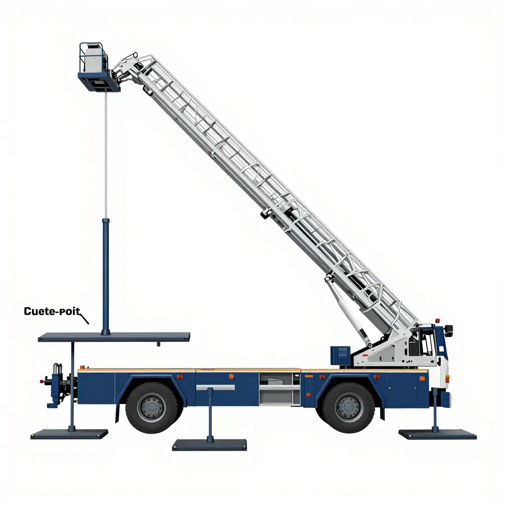
The path from boom to ground runs through the truck. The boom and turntable pass their weight and torque into the subframe and chassis, which send the load sideways along the outrigger beams as they reach outward. Vertical jacks then push down on the pads and lift the truck until the tires unload or clear the ground. The pads spread that concentrated force over enough soil or pavement to keep the ground from failing.
Main components of a typical outrigger set:
- Outrigger beams – box beams that slide, telescope or swing outward to widen the truck’s footprint.
- Vertical jacks – hydraulic cylinders that lower the pads and level the chassis.
- Pads (floats) – ground-contact plates that distribute jack force over a larger area.
- Turntable and subframe – the interface that feeds boom moment into the chassis and out to the beams.
- Interlocks and sensors – switches, pressure readings and level indicators that confirm full deployment.
What an Outrigger Fault Is
An outrigger fault is any condition that stops the system from reaching or holding its correct deployed state. The faults fall into a few families. Mechanical faults include bent or jammed beams and cracked pads. Hydraulic faults include leaking cylinders, internal bypass, and pump or valve problems that let a jack drift. Sensor faults include false “deployed” signals or disabled interlocks that let the boom move before the truck is stable. Pad faults include sinking, tipping, or loss of ground bearing under the plate. Locking faults include pins and locks that fail to seat, letting a jack creep under load.
The outrigger set is the foundation of fire truck stability: the boom, the ladder, and the crew at the tip all depend on it, and a ladder’s working height means nothing if the footprint underneath is not solid (see how far a fire truck ladder can reach). Let one outrigger fail to hold and the safe operating envelope shrinks; operations stop until the truck is repositioned or repaired.
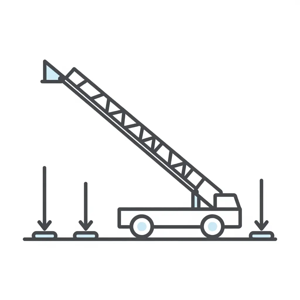
The diagram shows load moving through four beams and pads into the ground, with arrow length marking the reaction force at each pad. Because the load is rarely shared equally, each pad can exert a different bearing pressure – one of the setup checks crews make before raising the ladder.
Ground Bearing Pressure Fundamentals for Aerial Ladder Truck Operations
Ground bearing pressure is the force a truck transfers to the ground through each outrigger pad, expressed as force per unit area. It tells you whether the surface under the apparatus can support the truck while the boom is raised, extended, and rotated.
A truck’s operating weight – chassis, water, equipment, crew – combines with the loads from the boom, the bucket, and anything at the tip. Those forces resolve into concentrated reactions at each outrigger. Because the boom swings around the turntable, the reaction at any one outrigger changes continuously, and the most heavily loaded pad governs the design.
Each outrigger pad spreads its reaction over a contact footprint. Ground bearing pressure equals the reaction force divided by the pad’s footprint area, so a larger pad lowers the pressure for the same load. The ground’s ability to resist that pressure is the soil bearing capacity. When the imposed pressure exceeds it, the pad sinks, the truck settles, and stability is lost.
Soft, saturated, or frozen ground reduces safe bearing capacity. Saturated soil loses internal friction and cohesion, frozen ground may thaw and soften under load, and loose fill or hidden voids can collapse without warning. When conditions are uncertain, crews enlarge pads, add cribbing, or reposition to firmer surfaces.
Factors That Raise Ground Bearing Pressure
- Higher total apparatus weight and heavier boom or bucket loads
- Greater boom reach, elevation, or rotation away from the pad cluster
- Smaller outrigger pad footprint area
- Asymmetric loading, such as operating on only one side of the truck
- Weak, soft, saturated, or thawing soil beneath the pad
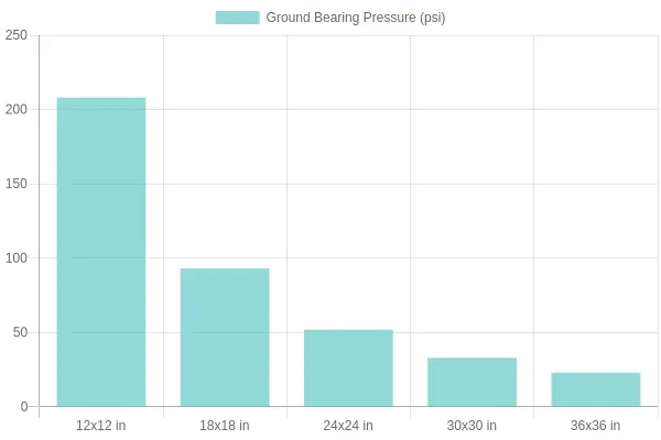
Reaction force, pad size, and soil type work together: higher reactions and smaller pads raise ground bearing pressure, while larger pads lower it. Matching pad size to the expected soil bearing capacity is the calculation that keeps the truck stable through the operation.
The values below are indicative only. Real capacity swings widely with moisture, base thickness, frost depth, and how a load spreads, so treat them as a starting point for a site assessment, not a final answer.
| Surface/Soil Type | Typical Safe Bearing Capacity (kPa) | Suitability for Aerial Outrigger Setup | Recommended Mitigation |
|---|---|---|---|
| Firm compacted gravel | 200 – 400 | Good – high stability for outrigger pads | Deploy standard pads and confirm the layer is compacted, not just surface-dressed |
| Asphalt (thick, intact with sound base) | 200 – 500 | Good where the base is sound and cool | Use outrigger pads to spread load; avoid hot or freshly laid asphalt that can deform |
| Dry clay (stiff, not cracked) | 150 – 300 | Moderate to good while dry | Reassess after any rain; larger pads help avoid edge punching |
| Loose sand | 50 – 150 | Poor to moderate – sinks and shifts | Crib with large timber or steel plates to widen the load footprint before jacking |
| Saturated soft soil | 20 – 50 | Poor – high sink and tipping risk | Apply oversized pads or cribbing, and stay clear of trench edges and backfill |
| Frozen ground | 100 – 600 (highly thaw-dependent) | Variable – risky in a partial thaw | Monitor for thawing and place cribbing; be extra cautious in spring conditions |
Caption: Quick reference for ground bearing pressure and safe bearing capacity when judging outrigger placement before setup.
The goal on scene is to match the pad footprint to the surface under it. Soft ground rarely fails all at once; it creeps, and a slowly sinking outrigger can tilt a fully extended ladder with people on it. Inspectors can use this table during size-up and post-incident review, and the same logic applies on bridges and other uneven surfaces, where decking and embankments change the load picture quickly.
Slope Checks and Stability Limits
Setting up on uneven ground is a stability calculation, not just a parking decision. Slope checks determine whether the outriggers can be deployed safely, and everything depends on one reference point: the center of gravity.
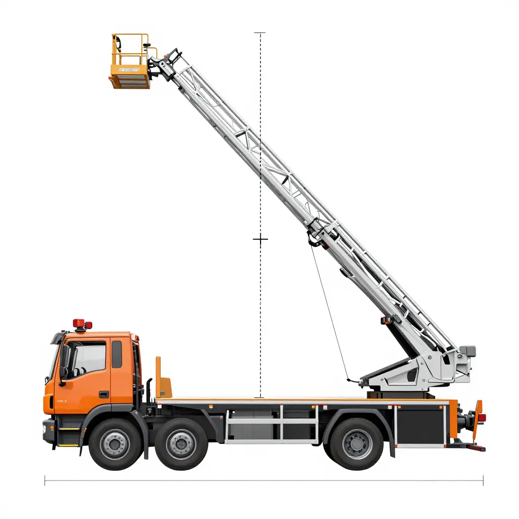
How Longitudinal and Lateral Grade Move the Center of Gravity
A parked ladder truck’s center of gravity is set by its mass distribution, the ladder’s position, and the load it carries. When the ground pitches, that point moves.
- Longitudinal grade (front-to-back): the center of gravity migrates toward the lower end of the chassis, changing the weight carried by each axle and each outrigger.
- Lateral grade (side-to-side): the center of gravity leans toward the low side, reducing the stabilizing moment that keeps the truck planted.
The steeper the grade, the farther the center of gravity moves from its design position and the smaller the margin against tipping.
Why Manufacturers Publish a Maximum Slope
Manufacturers publish a maximum slope because the chassis, beams, and hydraulic system are rated for a defined load geometry. An extended ladder adds leverage: the farther it reaches, the farther the effective center of gravity travels from the truck’s footprint. The published limits are conservative, leaving a safety factor for real conditions.
Reading the Inclinometer or Level Indicator
Most apparatus carry an inclinometer, or bubble level, within the operator’s view. It reads grade on two axes, and both need checking.
- Position the truck, apply the parking brake, and chock the wheels.
- Read the level indicator on both the longitudinal and lateral axes.
- Compare each reading against the manufacturer’s published maximum slope.
- If within limits, deploy the outriggers and confirm each pad seats firmly and evenly.
Mild Grade Versus the Tipping Boundary
On a mild grade the pads still seat with a predictable pressure distribution and the load stays inside the safe envelope. As slope increases toward the tipping boundary, the down-slope outriggers carry disproportionate load while the up-slope pads may lose contact: one pad compresses the ground while its opposite lifts.
Cribbing or shoring under the low pads corrects grade by raising them to a common plane and restoring a level load path. It is a temporary fix and must be rated for the load and the ground conditions.
Slope, reach, and stability also set how far a ladder can safely be extended; see how far a fire truck ladder can reach.
How Boom Angle Shifts the Outrigger Reaction Load
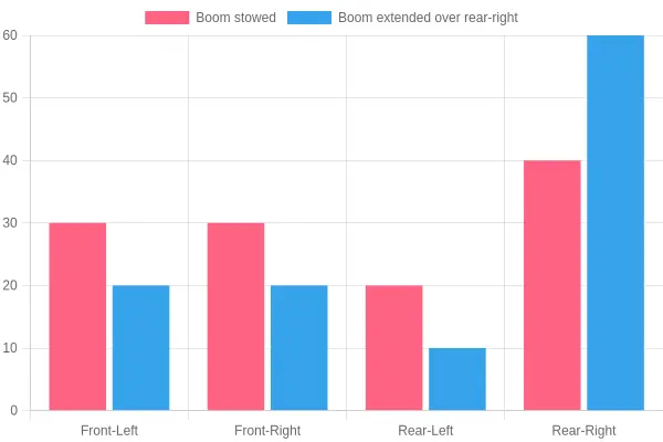
As the boom climbs and swings over a corner, the weight it carries does not stay evenly spread across the four pads. The chart below plots outrigger reaction load on a typical aerial ladder truck across five boom angles, comparing the pad closest to the boom with the one diagonally opposite.
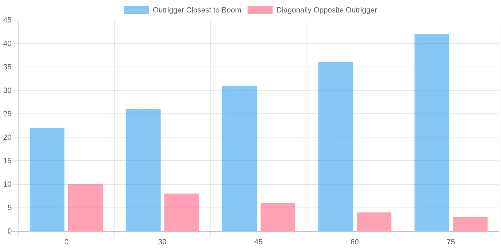
Outrigger reaction load versus boom angle: the pad closest to the boom reads 22 tons at 0 degrees and 42 tons at 75 degrees, while the diagonally opposite pad falls from 10 tons to 3 tons.
| Boom Angle (degrees) | Outrigger Closest to Boom (tons) | Diagonally Opposite Outrigger (tons) |
|---|---|---|
| 0 | 22 | 10 |
| 30 | 26 | 8 |
| 45 | 31 | 6 |
| 60 | 36 | 4 |
| 75 | 42 | 3 |
Why the Numbers Matter on Scene
The numbers matter because ground bearing pressure is not uniform. At a low boom angle the weight is shared, but once the ladder reaches steep angles or rotates toward a corner, a single outrigger can absorb most of the load. That concentrated reaction is what punches through soft soil, cracks a driveway, or sinks a float.
For crews and inspectors, three points stand out:
- The closest pad does the heavy lifting. Its load nearly doubles between 0 and 75 degrees, so a pad rated for average conditions can be overloaded during a high-angle rescue.
- The diagonal pad unloads. Falling to just 3 tons, it can even lift slightly – the reason slope and cribbing checks come before the boom goes up.
- Rotation compounds the effect. Swinging the boom over a different corner changes which pad becomes critical, so a setup that looked stable at the station may not hold on scene.
Planning a safe, stable set starts with knowing how far the ladder actually reaches at those angles.
Common Outrigger Fault Types on Aerial Ladder Trucks
Outrigger faults affect stability during deployment, so knowing the most frequent failure modes helps with safer operation and maintenance planning. The main types seen in stabilization systems:
- Hydraulic cylinder seal leakage – Worn or damaged seals allow hydraulic fluid to escape, reducing the force that holds the outrigger in position. This can lead to slow settling or gradual loss of lift under load.
- Slow or incomplete beam extension – The horizontal beam may extend unevenly or not reach full travel, often caused by internal wear, restricted flow, or debris in the cylinder. Partial extension reduces the effective footprint of the stabilization system.
- Outrigger pad detachment or cracking – Pads can separate from the foot or develop cracks from repeated impact and stress. A damaged pad reduces contact area and may cause uneven ground pressure.
- Locking pin or mechanical interlock failure – Pins may seize, bend, or fail to seat properly, preventing the outrigger from locking securely. A missing or ineffective interlock can allow unintended movement.
- Load or pressure sensor drift – Sensors may gradually lose calibration, reporting inaccurate force or pressure readings. Drift can mislead operators about the true load carried by each outrigger.
- Control valve malfunction – Sticking, leaking, or internally worn valves disrupt the flow of hydraulic fluid to the cylinders. This can cause unresponsive, erratic, or one-directional outrigger movement.
- Alarm or warning system failure – Faulty sensors or wiring can disable the interlocks and audible alerts that signal improper deployment. Without working warnings, operators may proceed without a clear stabilization.
- Grounding or cribbing slippage – Cribbing can shift, sink, or slide on soft or sloped surfaces, allowing the pad to lose contact. Slippage undermines the load distribution that the aerial ladder truck relies on.
These faults can survive routine checks for several reasons. A visual inspection may confirm that an outrigger extends and the pad touches the ground without verifying that it holds full working pressure or stays locked. Sensor drift and minor seal leakage develop gradually, often producing readings that still look acceptable. And because many checks focus on whether the system moves rather than how much load it can carry, subtle degradation can persist between detailed maintenance intervals.
How Outrigger Faults Convert into Rescue Delays
An aerial ladder can be raised and occupied only after its outriggers are fully deployed, mechanically locked, and verified against the ground. Until that sequence is complete, the ladder is a load path without a foundation. When a fault appears – a slow or failed extension, a pressure loss in the hydraulic circuit, an unseated pad, or a slope beyond the truck’s rated limits – the apparatus is not simply slowed down. It is unavailable for aerial work until the fault and the ground conditions are resolved.
The sequence from fault to delay
The sequence is unforgiving: each stage finishes before the next begins, and urgency does not compress any of them.
- Fault indication at setup – the operator identifies a short outrigger stroke, a soft or floating pad, or a load-sensing alarm during the deployment and slope check.
- Repositioning – the truck is driven off the pad and re-spotted, usually onto firmer pavement or a flatter grade that keeps ground bearing pressure within limits.
- Re-leveling and additional cribbing – jacks are reset, and cribbing or load-spreading mats are added to correct the grade and stabilize the footprint.
- Redeployment or alternate apparatus – if the fault cannot be cleared on scene, crews either establish a second setup point or request a different aerial unit entirely.
- Ladder raise and occupation – only after every outrigger passes verification can the ladder be raised, extended, and safely climbed.
Each step consumes critical minutes. Repositioning alone can take several minutes before the cab is shut down again, and adding cribbing under a partially extended jack is slow, deliberate work that cannot be rushed without risking a tip-over.
Operational consequences for crews
The practical effect is reduced aerial reach availability. A truck staged at the ideal corner may have to abandon that position, and the stream from the ladder or platform no longer covers the original target. Commanders switch tactics: a second setup point, a different face of the building, or an alternative apparatus with compatible reach and stabilization footprint. Ground ladders and exterior streams can substitute, but they cannot match the height or working platform an aerial provides.
For safety inspectors and fleet managers, this is an operational readiness problem, not a roadside inconvenience. An outrigger that is slow, leaking, or misrigged removes aerial capability from the first-alarm assignment before anyone reaches the fireground. Routine outrigger inspection, slope assessment training, and pre-planning of viable setup points keep these faults from turning into rescue delays.
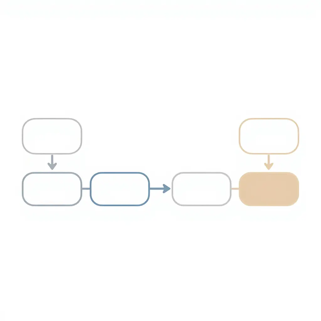
Figure 1. One failing stabilizer sets off a chain: detection, ladder hold, repositioning, added cribbing, redeployment, and finally delayed aerial operations. See how far a fire truck ladder can reach to gauge the reach lost while the crew resets.
Inspection and Maintenance Protocols That Prevent Outrigger Faults
Outrigger faults rarely appear without warning. They build through worn pads, drifting sensors, hydraulic seepage, and structural fatigue between deployments. A disciplined outrigger inspection and preventive maintenance program keeps a truck ready and prevents the delays that follow a failed setup, which can reduce the aerial ladder reach available at a scene. Because outrigger stability depends on the ground bearing pressure and slope conditions discussed above, these checks are the field complement to site assessment.
For firefighters and emergency response teams, a sound procedure runs in this order:
- Perform a pre-deployment visual and functional check. Confirm pads, hoses, cylinders, pins, and locking mechanisms are intact and free of leaks or damage, then cycle each outrigger through its full range before committing to an elevated operation.
- Inspect pad and ground contact condition. Verify pads are not cracked, deformed, or contaminated, and cross-reference the surface with the ground bearing pressure estimates established during setup planning.
- Verify sensor and slope indicator function. Check that level and load sensors read correctly and are calibrated to manufacturer tolerances, since inaccurate readings undermine the slope checks that determine safe deployment.
- Complete scheduled hydraulic and structural inspections. Examine cylinders, seals, welds, and mounting points at defined service intervals to catch seepage or fatigue before it becomes a fault.
- Conduct load testing at required intervals. Follow the manufacturer schedule and applicable standards to confirm the system holds rated capacity under controlled conditions.
| Protocol | Typical interval | Focus area |
|---|---|---|
| Pre-deployment check | Every shift or before each deployment | Visual and functional |
| Hydraulic and structural inspection | Monthly to quarterly | Cylinders, seals, welds |
| Sensor calibration | Per manufacturer schedule (often quarterly) | Level and load sensors |
| Pad condition check | Each inspection cycle | Wear and deformation |
| Load testing | Annually or per applicable standard | Rated capacity |
Inspectors and crews verify outrigger integrity by documenting each check, comparing sensor output against baseline readings, and reviewing load test results against the manufacturer’s rated capacity. Followed consistently, these protocols turn outrigger inspection into routine upkeep instead of a reaction to failure, and preventive maintenance cuts the risk of rescue delays from a truck that cannot be set up safely.
When outriggers fail, the cause is almost never a single source. Breaking down the data shows where the risk clusters.
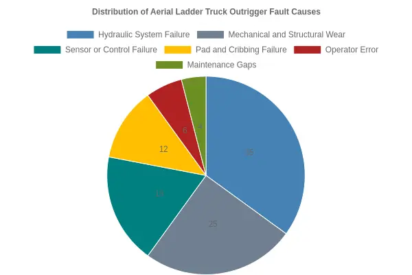
Caption: Hydraulic system failures and mechanical or structural wear together account for roughly 60% of the incidents in this breakdown. Both categories are wear-driven, so most of these failures are predictable and preventable through disciplined inspection cycles, fluid checks, and load testing. For more on how equipment condition affects readiness, see why regular apparatus checks matter.
On scene, the outrigger system transfers the weight of the apparatus, the elevated boom, and any tip load into the ground. Because these vehicles are heavy and wide, knowing how big fire trucks are in length, width, and gross vehicle weight helps crews work out where each pad should sit. Mast and boom height matter too: how high a fire truck stands governs how much leverage the aerial applies to its stabilizing legs.
Outrigger loads rise with the length of the aerial device and the volume of water being delivered. How far a fire truck ladder can reach explains why a fully extended boom produces a greater overturning moment, and fire truck pump capacity shows how water weight and nozzle pressure add strain. Together, these factors make slope checks and ground bearing pressure calculations necessary before the aerial is raised.
Stabilization matters most during fire truck operations on bridges, where the running surface may be an elevated deck with limited structural support beneath it. Soft soil, steep grades, or compromised pavement can make a pad sink or shift, forcing crews to reposition or abort and delaying rescue.
Frequently Asked Questions About Aerial Ladder Truck Outrigger Safety
What is ground bearing pressure in aerial ladder truck operations?
Ground bearing pressure is the load an outrigger pad applies to the ground, expressed as force per unit area, such as pounds per square inch. It rises as the aerial extends and the center of gravity shifts away from the chassis. When the pressure exceeds what the soil, asphalt, or concrete can support, the pad can sink or shift. Crews check it to confirm the surface is strong enough before raising the ladder. For related capacity considerations on structures, see fire truck operations on bridges.
How often should outriggers be inspected?
Outriggers should be inspected at the start of every shift using a documented walk-around checklist. A qualified technician then performs a more detailed inspection monthly, quarterly, or on the manufacturer’s schedule. Any outrigger involved in a heavy deployment or unusual incident should be re-checked before its next use.
What slope is safe for outrigger deployment?
Most manufacturers specify a maximum operating slope, usually no more than a few degrees, and the exact figure is in the apparatus manual. Crews should check slope with a level or inclinometer before extending the outriggers, and pads should be fully seated and level even on graded ground. If the required slope exceeds the rated limit, relocate the setup or add supplementary stabilization.
How do outrigger faults cause rescue delays?
An outrigger fault can force a crew to abort or delay ladder deployment until the problem is found and corrected. Those minutes come out of the response while a fire or a trapped victim waits. Because aerial operations cannot proceed safely on unstable outriggers, one faulty component can push back the whole timeline.
Can cribbing fix poor ground bearing?
Cribbing spreads the load over a larger area and improves ground bearing pressure on soft or uneven surfaces. It only helps when it is correctly sized, stacked, and rated for the load, and it cannot compensate for severely unstable ground. Treat cribbing as a supplement, not a substitute for choosing a sound setup location.
What warning signs indicate an outrigger fault?
Warning signs include pads that sink, tilt, or fail to reach full extension, unusual noises during deployment, hydraulic fluid leaks, and error indicators on the outrigger control panel. Operators may also see the truck body shift or a warning light for a stability limit. Treat any of these as a possible outrigger fault and check before raising the aerial.
Key Takeaways: Protecting Aerial Ladder Truck Readiness
Outriggers are the foundation of aerial ladder truck stability. They transfer the load of the boom, ladder, and personnel outward to the ground and keep the apparatus level while the aerial is deployed. Compromise that system and everything resting on it becomes unpredictable.
How load reaches the ground matters as much as extending the stabilizers. Ground bearing pressure determines whether the surface can carry the concentrated weight delivered through each pad, and slope checks confirm the truck sits within manufacturer limits before anyone climbs. Neither step is optional; skipping either can turn a routine operation into a structural failure. For more on how surface conditions and load distribution shape response work, see fire trucks on bridges during emergency response.
Outrigger faults – seized beams, hydraulic leaks, worn pads, sensor errors – extend setup time and create rescue delays at the worst moment. The most reliable safeguard is disciplined inspection and preventive maintenance, which keep the stabilizer system dependable and the apparatus ready to respond.
In practice:
- Verify ground bearing pressure and complete slope checks before deploying the aerial device.
- Treat any outrigger fault as a critical defect and remove the truck from service until it is corrected.
- Build outrigger inspection into daily checks and scheduled preventive maintenance.
- Document stabilizer performance over time to anticipate faults that cause rescue delays.